Together with my college we have been building an electric cargo tricycle. We both have the same bike, the Babboe Big:

The bike will mostly be used to transport our children so speed is not important. That is why we chose the Smart Pie by Golden Motor

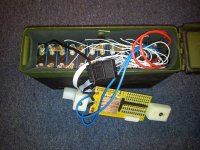
The battery was made with 12 GWL / Power WINA LiFePO4 3,2V 10Ah cells:
Hi-Tech industrial battery cell based on lithium technology - LiFePO4, high energy density and metal housing.
Nominal voltage of the cell is 3,2 V and the operational voltage is 2,5 - 3,65 V.
The maximum charging voltage for initial charge is 3,8 V.
Recommended subsequent charging is to 3.65 V.
The minimum voltage is 2.5 V.
Maximum discharge current is 2C continously and 3C peak (<15sec)
Operating temperature -20°C - 60°C (discharging)
More info: http://www.ev-power.eu/LiFePO4-small-cells/WINA-LiFePO4-Power-3-2V-10Ah-aluminium-case.html

So this should make a 36 V battery.
We charged all the cells individually like it is told on the EV-Power site. Initial charge = 3,8V 2,5A per cell
As a BMS / PCM we have the PMC-12S, 36V, LiFePO4, Phosphate BMS, 20-40A.
This was bought here: http://www.greenbikekit.com/bms-pcm/12s-e-bike-lithium-battery-bms.html
(the 20-40A version)
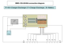
We connected the cells and BMS according to the diagram that came with the BMS.

We programmed the Smart Pie with the software you can download on the Golden Motor website. Here is an image of that interface. Our settings are NOT the same as those on the picture.

Our settings:
- Max Current Continuous 12 A
- Max Current Peak 15 A
- Motor type – BLDC (brushless) 120 degr.
- PAS high
- Motor Voltage 36 V
- FWD speed 100%
- REV disabled
- Regenerative Brake 116% (maximum)
The PAS sensor did not fit properly so the PAS does not work at this moment. But the Smart Pie came with a thump throttle so we could ride the bike.

I was the first to finish building the bike. The EV-bike did what it should. I went for a test drive and I was amazed about the speed it had. I drove 12,5 km in 34 minutes, that is with stoplights and other things that slow you down. I was very content with what I build.
My college finished his bike a bit later. But his showed problems. After he connected his battery and got on the bike to drive it would shut down within a 100 meters. After disconnecting the battery he could use it again but only for a few meters.
He checked all the wires but could not find anything. Because the bikes were the same and mine was working fine I said, give my your battery so I can check it.
After connecting it to my bike is also shut down within 100 meters.
Now the problems started with my bike as well. ??????
I put my battery back on and the bike drove fine again but my regenerative braking was gone. After a few kilometers I went over a small hill and the 15A fuse (in the Battery) gave in. I had a 20A fuse with me so I put that one in and drove on.
So it was the battery pack of my college that was not working like it should. We checked the battery and found that the cell on the negative end of the battery was dead 0,0V. ?????
At first I could drive 20 km easy with one charge but ever sins I connected the other battery the first battery indicator light on the thump throttle went out after a few 100 meters. So I also checked my battery and we found the same cell that died.
We checked all the wireing but everything was connected correct.
We checked if the BMS worked like it should by putting a laboratory power supply in the place where a cell was. Set it to 3,4V, hooked up the battery to a load and the turned the voltage down. At 2,1V the BMS shut the battery down like it said it would in the specs. Checked the other BMS and the same result
So both BMS are OK.
My college never programmed a maximum current. After connecting his battery to my bike the regenerative breaking settings were gone. So maybe all the settings were gone. So I reprogrammed the Smart Pie with the settings from above. We rebuild one battery at the expense of the other battery, charged it and put it on my bike. Again it drove like a charm. I went for a drive of about 15 km and everything seemed good. A day later we checked the battery and again the cell on the negative side was dead (0,0V)
What the hell is going on we are at a loss here. Can anybody help us?

The bike will mostly be used to transport our children so speed is not important. That is why we chose the Smart Pie by Golden Motor

The battery was made with 12 GWL / Power WINA LiFePO4 3,2V 10Ah cells:
Hi-Tech industrial battery cell based on lithium technology - LiFePO4, high energy density and metal housing.
Nominal voltage of the cell is 3,2 V and the operational voltage is 2,5 - 3,65 V.
The maximum charging voltage for initial charge is 3,8 V.
Recommended subsequent charging is to 3.65 V.
The minimum voltage is 2.5 V.
Maximum discharge current is 2C continously and 3C peak (<15sec)
Operating temperature -20°C - 60°C (discharging)
More info: http://www.ev-power.eu/LiFePO4-small-cells/WINA-LiFePO4-Power-3-2V-10Ah-aluminium-case.html

So this should make a 36 V battery.
We charged all the cells individually like it is told on the EV-Power site. Initial charge = 3,8V 2,5A per cell
As a BMS / PCM we have the PMC-12S, 36V, LiFePO4, Phosphate BMS, 20-40A.
This was bought here: http://www.greenbikekit.com/bms-pcm/12s-e-bike-lithium-battery-bms.html
(the 20-40A version)
We connected the cells and BMS according to the diagram that came with the BMS.

We programmed the Smart Pie with the software you can download on the Golden Motor website. Here is an image of that interface. Our settings are NOT the same as those on the picture.

Our settings:
- Max Current Continuous 12 A
- Max Current Peak 15 A
- Motor type – BLDC (brushless) 120 degr.
- PAS high
- Motor Voltage 36 V
- FWD speed 100%
- REV disabled
- Regenerative Brake 116% (maximum)
The PAS sensor did not fit properly so the PAS does not work at this moment. But the Smart Pie came with a thump throttle so we could ride the bike.

I was the first to finish building the bike. The EV-bike did what it should. I went for a test drive and I was amazed about the speed it had. I drove 12,5 km in 34 minutes, that is with stoplights and other things that slow you down. I was very content with what I build.
My college finished his bike a bit later. But his showed problems. After he connected his battery and got on the bike to drive it would shut down within a 100 meters. After disconnecting the battery he could use it again but only for a few meters.
He checked all the wires but could not find anything. Because the bikes were the same and mine was working fine I said, give my your battery so I can check it.
After connecting it to my bike is also shut down within 100 meters.
Now the problems started with my bike as well. ??????
I put my battery back on and the bike drove fine again but my regenerative braking was gone. After a few kilometers I went over a small hill and the 15A fuse (in the Battery) gave in. I had a 20A fuse with me so I put that one in and drove on.
So it was the battery pack of my college that was not working like it should. We checked the battery and found that the cell on the negative end of the battery was dead 0,0V. ?????
At first I could drive 20 km easy with one charge but ever sins I connected the other battery the first battery indicator light on the thump throttle went out after a few 100 meters. So I also checked my battery and we found the same cell that died.
We checked all the wireing but everything was connected correct.
We checked if the BMS worked like it should by putting a laboratory power supply in the place where a cell was. Set it to 3,4V, hooked up the battery to a load and the turned the voltage down. At 2,1V the BMS shut the battery down like it said it would in the specs. Checked the other BMS and the same result
So both BMS are OK.
My college never programmed a maximum current. After connecting his battery to my bike the regenerative breaking settings were gone. So maybe all the settings were gone. So I reprogrammed the Smart Pie with the settings from above. We rebuild one battery at the expense of the other battery, charged it and put it on my bike. Again it drove like a charm. I went for a drive of about 15 km and everything seemed good. A day later we checked the battery and again the cell on the negative side was dead (0,0V)
What the hell is going on we are at a loss here. Can anybody help us?

