Ethanator10000
1 mW
This is probably a stupid question, but I can't find any specific instructions and am curious as to how others do it:
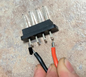
What's the best practice for soldering my grin baserunner to the terminals in my downtube battery cradle? There are 4 pins (2 +ve, 2 -ve) and of course two wires. Should each wire just be soldered to one pin each? Or should each wire be connected to both of the respective positive and negative pins? If it's the latter, what's the best technique for that?

What's the best practice for soldering my grin baserunner to the terminals in my downtube battery cradle? There are 4 pins (2 +ve, 2 -ve) and of course two wires. Should each wire just be soldered to one pin each? Or should each wire be connected to both of the respective positive and negative pins? If it's the latter, what's the best technique for that?