[SOLVED] Help: Cycle Analyst speed limiting issue

danoussh

10 mW
Joined
Aug 20, 2013
Messages
23
Location
France
Hi,

I'm seeking help and guidance with an issue I'm having on my ebike setup.

My original problem/symptom was something was limiting my acceleration and motor power. My throttle was wide open (WOT), I would build up speed, then as I arrived around 40Km/h I could feel the motor cutting rapidly on and off. So I though it could be CA's AmpLimit, but no as it was cutting around 33Amps while my AmpLimit is 40Amps, but I also tried with a higher AmpLimit like 50Amps. Still same symptom.
Thinking it could be my controller, I tried reducing or increasing my phase/battery current settings on the controller but to no avail. I still get the symptom.
At this stage I thought about disconnecting the CA, which I did. The problem was gone. My motor was running smoothly. So I seems to be my Cycle Analyst.

At this stage, I start observing a little more the information from the CA to discover that my top speed was +150Km/s each time I end my rides. I do ride fast, but not that fast :p. I also noticed that the symptom disappear when I twist throttle less than 3/4.
As I check my CA when I ride, I noticed my speed is not right. It sometimes displays spikes values like 90Km/s when in reality I'm at 40Km/h.
So now I know the limiting effect on the motor is the Cycle Analyst that is speed limiting because it's reading some speed values that are above the CA's SpeedLimit setting (set to 99Km/s).

I checked my pole setting in the CA, it's set to 28 as my motor is an GoldenMotor Magic Pie 3 (MP3). To make sure, I counted 28 poles by measuring the ouput of one of the hall sensors on the motor. If i'm correct, the motor has 28 south poles and 28 north poles which hads up to 56 poles.

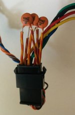
I also check my hall sensors on the motor. They all sense the wheel turning. I have 4.80V on power pins (Negative and positive.), and measure 5V on each hall sensor output signal wire. I would say that are working fine.

Does anyone have an idea what the problem is? Why do I have inconsistent and spikes in my speed values which causes my cycle analyst to limit the motor?


Setup:
Bike: Rockrider 6.3
Motor: Golden Motor - Magic Pie 3
Controller: Lyen - 12fet x 4110 MOSFET Extreme Modder Controller
Battery: 22s8p - Li-ion INR18650-25R (91Volts full charged.)
Cycle Analyst v2.4 - Direct plug to controller. (Originaly v2.3, but recently upgraded to v2.4)
Thumb throttle from ebay (Hall Effect)
 
It sounds like the hall signals are full of noise (probably from being in parallel with phase wires, but possibly from magnetic fields inside the motor itself).

Separating the hall wires out of the cable that houses the phase wires, and isolating them with a shield that's grounded at one end (the controller end is probably easiest), may prevent or at least minimize induced noise from phase signals in the wiring (it wont' stop anything inside the motor).


You may be able to add a small ceramic capacitors (0.1uf or less) from the signal wire to ground, right at the CA's speedo input connection (like at the 6pin CA connector) to help with this. (a cap at the other end might help too, but it's ahrder to do inside the motor).

Alternately, you can use an external speedo sensor, like the SA version of the CA uses. Any NO reed switch mounted near enough to a wheel to detect a magnet mounted on a spoke or hub will do; you disconnect the speedo wire of the CA from the controller, and isntead wire it (and ground) to that reed switch. Change number of poles to 1 if you use one magnet, or to however many magnets you use (I use three on SB Cruiser for a bit better response to speed changes).
 
amberwolf said:
It sounds like the hall signals are full of noise (probably from being in parallel with phase wires, but possibly from magnetic fields inside the motor itself).

Separating the hall wires out of the cable that houses the phase wires, and isolating them with a shield that's grounded at one end (the controller end is probably easiest), may prevent or at least minimize induced noise from phase signals in the wiring (it wont' stop anything inside the motor).

I had not thought of signal noise. Would that explain having issue at higher RMP rate? I mean I only get this once I pick up speed. Also, it doesn't seem to fail when I run the motor unloaded.
Is there a difference on strength of the magnetic field when it's a low RPM compared to high RPM? I guess it would be due to more power in the winding as I accelerate and the controller sends out more power.

There is one thing to note, my hall wires run along the phase wires but in seperate cables. The phase wires run in un-shielded 2.5mm2 cross section wire while the hall wires run in ethernet cable UTP completely un-shielded.
So I think the culprit may well be using un-shielded ethernet cable. I used to have SFTP Cat6 ethernet cable (double shielding, core and each pair.). I will revert back to this type of cable.

amberwolf said:
You may be able to add a small ceramic capacitors (0.1uf or less) from the signal wire to ground, right at the CA's speedo input connection (like at the 6pin CA connector) to help with this. (a cap at the other end might help too, but it's ahrder to do inside the motor).

Alternately, you can use an external speedo sensor, like the SA version of the CA uses. Any NO reed switch mounted near enough to a wheel to detect a magnet mounted on a spoke or hub will do; you disconnect the speedo wire of the CA from the controller, and isntead wire it (and ground) to that reed switch. Change number of poles to 1 if you use one magnet, or to however many magnets you use (I use three on SB Cruiser for a bit better response to speed changes).

I will try a with a capacitor before changing the wire. If I understood correctly, the goal would be to place a cap between each of the hall's signal wire and the ground/negative wire from the controller? I understand that the cap will reduce spikes in electrical signals which will kinda smooth out the signal and prevent false signals. Does this act like a pull down resistor but for high frequency signals/spikes?

Thanks for taking time to read and giving me a possible solution. :wink:
 

Attachments

  • Ceramic-capacitors-0.1uF.jpg
    Ceramic-capacitors-0.1uF.jpg
    58.4 KB · Views: 686
  • Hall-wires-with-capacitors.jpg
    Hall-wires-with-capacitors.jpg
    39.5 KB · Views: 686
danoussh said:
I had not thought of signal noise. Would that explain having issue at higher RMP rate? I mean I only get this once I pick up speed. Also, it doesn't seem to fail when I run the motor unloaded.
Is there a difference on strength of the magnetic field when it's a low RPM compared to high RPM? I guess it would be due to more power in the winding as I accelerate and the controller sends out more power.
It's not so much the strenght of the field, but the noise is a higher frequency and that's the kind of thing that is easier to pass a longer distance / induce into other wires.

The stator field is actually stronger at lower speed, under acceleration from a stop, because of the current in the phase wires, and very little back-emf (BEMF) from the spinning magnets in the rotor.

As speed increases, current induced into the phase wires (or rather, windings) by the rotor magnets increases, opposing the stator phase currents, then the field from those decreases; etc.

The stator currents are lower when the motor is unloaded vs loaded, as well.


There is one thing to note, my hall wires run along the phase wires but in seperate cables. The phase wires run in un-shielded 2.5mm2 cross section wire while the hall wires run in ethernet cable UTP completely un-shielded.
So I think the culprit may well be using un-shielded ethernet cable. I used to have SFTP Cat6 ethernet cable (double shielding, core and each pair.). I will revert back to this type of cable.
UTP would help on it's own, if each hall had it's own ground from inside the motor all the way to inside the controller. Most axles don't have room fro that, though.

Keep in mind that almost all hubmotor systems use unshielded hall signal, ground, and power wires running within the same cable housing as the phase wires, often twisted up together with them, and neither the CA nor the controllers have trouble with them. So why the problem happens in your case and not most others, I dunno...but it does happen now and then in some systems. (like with Cyclone systems, that sometimes have controller glitches from hall noise)


FWIW, the problem could instead be in teh hall power itself, severe noise induced there causing glithces in sensor operation, but it's much less likely than noise directly induced into the signal lines. Capacitor on those lines can help, if that's the issue, but it probably isn't.


I will try a with a capacitor before changing the wire. If I understood correctly, the goal would be to place a cap between each of the hall's signal wire and the ground/negative wire from the controller? I understand that the cap will reduce spikes in electrical signals which will kinda smooth out the signal and prevent false signals. Does this act like a pull down resistor but for high frequency signals/spikes?
Sort of, yes. More like a damper on a spring, to help keep it from oscillating as much or as far.

As far as the caps go, unless you're having trouble with the controller, you really only need one on the CA's speedo signal line, on the CA connector itself, from the speedo wire to ground.

YOu can certainly put them on the motor/controller hall connector, if you prefer.
 
My problem is fixed.

I first replaced the hall cable with new FTP ethernet cable (foil shielding around all the wire pairs at once. Each pair are not foiled.), brand new jst-sm connector. Also made sure the cable shielding foil was connected to the ground pin in order for the shielding to work. I soldered the new cable 6cm before the hall pins and then it goes right up to the controllers' hall cable connector but still rides along the phase wires. Not much I can do about the phase wire running along the hall wire, I could separate them a little but I'm limited in space.

At this point, the symptoms were still there. The cycle analyst was occasionally displaying spikes in speed values as wells as max speed values of 120km/h. So I though maybe I could test the capacitor idea. I had already tested this before replacing the hall cable but that didn't work. Turns out it still didn't fix the issue even with new cable. :(

So to recap, the cable is new, soldered and connected, tested continuity of wires and shield, installed capacitors on hall connector. But the problem is still there.

So I tried to to add a capacitor on the cycle analyst connector grounding the yellow wire (Pin 5 - Speed) to the ground/negative black pin (Pin 2). This fixed the issue. I no longer have any speed value spikes and the motor doesn't cut anymore. :D

I've ridden about 80km since the last fix and I have not had one error on the cycle analyst. At the moment, the fix is just temporary and will not last for ever in the condition I left it. The caps are just inserted in the connector like in my picture in previous post and all the cables around the controller and just strapped together and covered with a bin bag for waterproofing. I've ordered halls (SS41F) from aliexpress (https://aliexpress.com/item/10PCS-SS41-SS41F-TO3-SENSOR-SS-HALL-EFFECT-BIPOLAR-NEW-GOOD-QUALITY/32687538773.html) and I'll install them with capacitors inside the motor. Maybe I'll move the cycle analyst cap inside the cycle analyst or inside the controller instead of leaving it on the connector.

Anyway, I suspect the halls are getting old and may not be working perfectly. Or maybe they are getting too much interference from the motor. I was sometimes getting some grinding effect from the motor which I think may just be some bad battery/phase tuning. Now I understand I need to tune the controller first without the CA, then configure the CA.
I suspect that maybe bad tuning could cause extra unnecessary interference which are picked up by the halls or wire, not to mention extra heat. Maybe if I re-tune the controller before replacing the halls and remove the caps, then the spikes may disappear. If not, I'll just leave the caps and replace the halls.

Thank you Amberwolf. Your help is gratefully appreciated, I enjoyed several ride since. Feels good to have working ebike.
 
Back
Top