Suggestions? Blew the fuse on BBSHD controller now what?

furcifer

10 kW
Joined
Dec 21, 2018
Messages
723
So I had a cracked XT90 I should have changed (don't put off today what you're going to blow up tomorrow). It was cold and dark and I managed to get it in backwards. Pop.

The inline fuse popped. Bafang uses a slowburn 250V 30A fuse (for clothes dryers?) soldered to a PCB and shrink wrapped. Since there isn't much wire between the controller and the fuse I need to get this right the first time.

edit: I was looking at the solar panel fuse holders but they're too big. Anyways, I'm just looking for suggestions on how to replace this. Changing the fuse might be my only option. I'm just not sure I I can do it with the tools I have.
 
Last edited:
They used that fuse for a reason, to protect the system.

I don't recommend changing it for a higher rating--if you find you blow it in normal operation, then it means the system is being used outside it's intended abilities, and using a higher rated fuse essentially bypasses the protection the original gave. It'd still blow in situations like the one you just had, but wouldn't in a simple small overload situation, and if other controller / system protections didn't work for any reason, other system parts could fail that are much harder and more expensive to replace, as well as harder to troubleshoot and locate all of.


Fuse voltage simply means it is guaranteed to break a circuit at that voltage and keep it from arcing and continuing to flow current. So it has to be rated *at least* as high as the worst-case voltage the system would ever see under any conditions, and preferably higher.

They're also rated for DC or AC or both; AC goes to zero volts a certain number of times per second, DC never does (while powered on), so the AC rating is with that expectation, and it may not be capable of breaking a DC circuit at that same voltage, usually something much lower. If it has a dual rating, it might be something like 250VAC / 50VDC, etc. If there's no DC rating, it's a (possibly educated) guess as to what it's voltage limit would be.


Fuses don't work by watts.

They're rated for a certain amount of current for a certain amount of time; there's a chart for this on the fuse manufacturer site. Bussman are fairly easy to find and read. For instance, if your fuse is like this one
1707068715363.png
then this spec sheet linked on that page
says about time vs current vs rating:
Electrical Characteristics
Rated Current % of Amp Rating Opening Time
1/10 - 30A 110% 4 hours. min.
135% 60 minutes max.
1/10 - 2A 200% 5 seconds max.
2.5 - 30A 200% 2 minutes max.

Meaning if the fuse is rated for 15A, then you could use 110% of that , or 16.5A, for at least 4 hours before it could blow. You could use 135% of that, or 20.25A, for an hour, max. 200% or 30A, for 2 minutes max. (max means it could below before that, but isn't guaranteed to, but will blow by that time under that continuous current).

There's also a chart for current vs time:
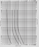
1707068841612.png


Also, most of those fuseholders are garbage and will cause you problems you never imagined--voltage drop, overheating, intermittent connections, arcing, fire, etc.

If the fuse is soldered in...I'd stick with that method.

If you must change it to a fuseholder, get a *very good*, very well-made fuseholder designed for the intended usage, from a reputable dependable seller (not amazon, ebay, ali*, etc)--it's going to cost more, but it will work and keep working.
 
Last edited:
Well you'd think it was there for a reason but I have 2 spares, one with a fuse and one without. (both with lights, the one I'm using doesn't have a light wire. So I have 3 different versions of the controller)

Fuses are rated for voltage as well. The fact that Bafang is using a 250V fuse in a 52V circuit is what is throwing me of. That's probably the AC rating so 125V equivalent but you can't tell by looking at the fuse. And from what I can tell these 250V fuses are basically only used in 220V appliances. There's literally no fuse holders for 250V, which is probably when Bafang has it soldered to a PCB and covered in shrink wrap. They don't exist. It might also explain why one of my controllers doesn't have a fuse, I believe it's the newest one of the bunch.

I had an old positive lead with a fuse so I just spliced it in. It should get me through until next winter. I live in the salt belt and when the snow turns to slush things start falling apart. It is shocking how quickly salt can eat through Copper Clad Aluminum. I like XT connectors but they are designed for fairweather RC enthusiasts and not 4 season cyclists.

Thanks for your post though, I think it was very informative. I still don't understand the difference between a fast and slow fuse. Mainly because I just plugged my battery in reverse and I didn't even draw any amps. But still the fuse popped in time to protect my controller. I guess they work slow in forward and fast in reverse but this is still a bit beyond what I know.
 
Thanks for your post though, I think it was very informative. I still don't understand the difference between a fast and slow fuse. Mainly because I just plugged my battery in reverse and I didn't even draw any amps. But still the fuse popped in time to protect my controller. I guess they work slow in forward and fast in reverse but this is still a bit beyond what I know.
You did draw amps or the fuse would not have blown. A fast blow fuse will immediately disconnect the circuit when an overcurrent occurs. That is to protect the circuit and it has to blow faster than the components it is trying to protect. A slow blow fuse takes longer to blow and can survive brief spikes in the current. It will prevent fires from a short circuit, but it will not protect the circuits as well.
 
Fuses are rated for voltage as well. The fact that Bafang is using a 250V fuse in a 52V circuit is what is throwing me of.

If you read my post, it shouldn't throw you off.

You should *always* use a fuse rated higher in voltage than your circuit has (as much higher as practical).


And from what I can tell these 250V fuses are basically only used in 220V appliances. There's literally no fuse holders for 250V, which is probably when Bafang has it soldered to a PCB and covered in shrink wrap. They don't exist.

It doesn't matter what the fuse *holder* is rated for, in voltage, as it never sees any voltage potential. Only the fuse itself does, and that only happens after it blows.

The fuse holder is simply designed for a specific kind of fuse and mounting application.

A fuse holder may be designed for a certain *current*, and specify only to use fuses lower than a certain rating in them, or it may be designed to work with any fuse of that mechanical type rating (and be able to handle the max current that type is made for).

If the fuse holder is made for a specific voltage, it means that it's conducting parts are close enough together that an arc could form and maintain itself across them at any voltage higher than that. There's no reason for them to build a fuse holder with it's conducting parts any closer together than the actual fuse terminals, so the fuse terminals should be the only thing in this part of the circuit that have a relevant voltage rating.


If your fuse holder sees a voltage across any part of it (when the fuse is not blown), it's either defective or the fuse is defective or installed wrong.


It might also explain why one of my controllers doesn't have a fuse, I believe it's the newest one of the bunch.
That one probably has a surface mount fuse instead, or a polyfuse (self-resetting). Or they cheapened the design to save money and just left it out. (not uncommon).


Thanks for your post though, I think it was very informative. I still don't understand the difference between a fast and slow fuse. Mainly because I just plugged my battery in reverse and I didn't even draw any amps. But still the fuse popped in time to protect my controller. I guess they work slow in forward and fast in reverse but this is still a bit beyond what I know.
They work exactly the same in both directions.

When you connected the battery in reverse, you drew so many amps it blew the fuse, because FETs are diodes in reverse, so they make essentially a short circuit across the battery.

The chart for any specific fuse (like I included in my previous post) shows you what will happen under various currents.

Manufacturers like Bussman also have manuals on how to choose a fuse for a specific application. (one such document is linked on the page I linked to.)
 
Last edited:
You did draw amps or the fuse would not have blown. A fast blow fuse will immediately disconnect the circuit when an overcurrent occurs. That is to protect the circuit and it has to blow faster than the components it is trying to protect. A slow blow fuse takes longer to blow and can survive brief spikes in the current. It will prevent fires from a short circuit, but it will not protect the circuits as well.
Well yah, but there was no load, the motor didn't move. And it was nowhere near 30A let alone the 60A I usually pull through that fuse.
 
By wiring it in reverse you had a dead short circuit, regardless of the motor not moving. The instantaneous current flow would have been the maximum current that the battery could deliver. It’s why the fuse blew.
 
Well yah, but there was no load, the motor didn't move.


And it was nowhere near 30A let alone the 60A I usually pull through that fuse.
Doesn't matter. The controller doesnt' even have to be "on", if the battery is connected to teh main B+ and B-, but in reverse, for this to happen.

As already noted the FETs would be diodes across the reversed battery, effectively shorting it out by placing about a 1.5v drop across whatever the battery voltage was. If those aren't enough, the electrolytic capacitors would add their own current path.


If you don't believe us, go wire up a battery backwards across a controller's main power leads with no protection (no fuse, no BMS, etc) and see which parts on the controller explode first. ;) If the shunts don't fall off or burn thru, and the solder doesn't melt off of anything first, or traces evaporate....

If you put a fast-reacting peak-hold ammeter capable of measuring high current (>100A) between the battery and the controller, youll see a huge current spike before it drops after the parts creating the current path are destroyed.

You can guesstimate the current by dividing the battery voltage (minus the diode drops of the FETs) by the wiring and shunt resistance between battery and controller. Best guess without any numbers for those is hundreds of amps or more.
 
If you read my post, it shouldn't throw you off.

You should *always* use a fuse rated higher in voltage than your circuit has (as much higher as practical).

You didn't read my post. There are 200 million cars on the road with 12V systems using 12V rated fuses. That's not close to always, that's almost the opposite correct?

It doesn't matter what the fuse *holder* is rated for, in voltage, as it never sees any voltage potential. Only the fuse itself does, and that only happens after it blows.


The fuse holder is simply designed for a specific kind of fuse and mounting application.

Yes exactly. You don't see how these two statements contradict one another? You're saying it doesn't matter what it is designed for, but it does.
A fuse holder may be designed for a certain *current*, and specify only to use fuses lower than a certain rating in them, or it may be designed to work with any fuse of that mechanical type rating (and be able to handle the max current that type is made for).
It's not the holder so much as the leads. And that's what I'm saying. The BBSHD controller uses 10AWG power wires. I can't find ANY fuse holders with 10AWG leads. They don't exist.

If the fuse holder is made for a specific voltage, it means that it's conducting parts are close enough together that an arc could form and maintain itself across them at any voltage higher than that. There's no reason for them to build a fuse holder with it's conducting parts any closer together than the actual fuse terminals, so the fuse terminals should be the only thing in this part of the circuit that have a relevant voltage rating.
Yah no. There are 6mmx30mm 12V and 5mmx20mm 250V fuses. (radius and length)


If your fuse holder sees a voltage across any part of it (when the fuse is not blown), it's either defective or the fuse is defective or installed wrong.
Exactly.
That one probably has a surface mount fuse instead, or a polyfuse (self-resetting). Or they cheapened the design to save money and just left it out. (not uncommon).
There's not a lot of room in the controller to do that. But it's potted so you can't see anything. A diode seems like a more plausible explanation but who knows? Not me, that's why I'm asking around.
They work exactly the same in both directions.

When you connected the battery in reverse, you drew so many amps it blew the fuse, because FETs are diodes in reverse, so they make essentially a short circuit across the battery.

The chart for any specific fuse (like I included in my previous post) shows you what will happen under various currents.

Manufacturers like Bussman also have manuals on how to choose a fuse for a specific application. (one such document is linked on the page I linked to.)
Well no they don't. Under normal operating conditions I can pull 60A through that fuse, the motor gets hot and there is angular motion converted to linear motion causing acceleration. Work is done because electrons move from the battery to the stator.

When I put it in backwards no work is done but there is a very brief increase in heat due the resistance in the fuse which causes it to melt. That's the physics that is eluding me. Normally a fuse blows because you're pulling too many electrons from the battery through the circuit into the motor and stator. But backwards that's not the case at all. Obviously I'm missing something here and I don't know what to do other than just keep this fuse spliced in and hope for the best. Otherwise like I say there doesn't seem to be an easy swap. I can get a 12V fuse holder that will hold a 250V 6x30mm fuse, but it has 18AWG leads at best. Or I can get a 1000V that will hold a 10x40mm fuse that's way too big. (assuming I figure out the math).
 
By wiring it in reverse you had a dead short circuit, regardless of the motor not moving. The instantaneous current flow would have been the maximum current that the battery could deliver. It’s why the fuse blew.
OK, so what would the max current of a 60A controller be? I think it's about 100A instantaneously.

So is that how they determine the proper fuse? It still seems low. Assuming the the fuse is 250V 30A AC, which is 125V 30A DC, you're saying the instantaneous current from the battery when it was plugged in backwards was higher than 63.7A. Well that actually seems higher so I guess it makes sense.
 
Doesn't matter. The controller doesnt' even have to be "on", if the battery is connected to teh main B+ and B-, but in reverse, for this to happen.

As already noted the FETs would be diodes across the reversed battery, effectively shorting it out by placing about a 1.5v drop across whatever the battery voltage was. If those aren't enough, the electrolytic capacitors would add their own current path.


If you don't believe us, go wire up a battery backwards across a controller's main power leads with no protection (no fuse, no BMS, etc) and see which parts on the controller explode first. ;) If the shunts don't fall off or burn thru, and the solder doesn't melt off of anything first, or traces evaporate....

If you put a fast-reacting peak-hold ammeter capable of measuring high current (>100A) between the battery and the controller, youll see a huge current spike before it drops after the parts creating the current path are destroyed.

You can guesstimate the current by dividing the battery voltage (minus the diode drops of the FETs) by the wiring and shunt resistance between battery and controller. Best guess without any numbers for those is hundreds of amps or more.
lol, well yah I don't "believe" anything I don't understand. Frying a controller doesn't help me choose a fuse that will work in this application. I trust that you are correct but that doesn't explain if I should use a slow or fast burn fuse and at what voltage.
 
By wiring it in reverse you had a dead short circuit, regardless of the motor not moving. The instantaneous current flow would have been the maximum current that the battery could deliver. It’s why the fuse blew.
Actually now that I think about it this makes sense. I forget in reverse the electrons flow through the positive wire on the controller. The instantaneous peak current from the BMS would surge through the fuse. With a full battery that would have been more than the 250V 30A fuse could handle and it popped. Slow or fast burn wouldn't matter in the reverse configuration.

Based on these assumptions a 1000V 7.5A fuse should work similar to a 250V 30A, and have the same resistance.
 
Based on these assumptions a 1000V 7.5A fuse should work similar to a 250V 30A, and have the same resistance.
This isn't true. A 7.5A fuse will blow at 7.5A + the safety factor. A 30A fuse will blow at 30A + the safety factor. The voltage rating is not part of a calculation on when the fuse blows. It is just the maximum voltage that the fuse can be safely operated at and still perform to the manufacturers specifications.

Fuses function by passing the current through a filament or medium that is designed to melt when the current exceeds the rated current of the fuse plus a safety factor that the manufacturer determines. The formula used to calculate heat produced by a current is Joule's Law: P=I^2R and doesn't depend on voltage at all.
Wah? Ohm and Joule's laws are related. Voltage is still in there you've just replaced it with a different variable. I=P/V so P= (P/V)^2 *2R.
 
After a little more digging I was able to find a 6x30mm fuse holder without leads. I'll mod them to hold bigger wires and use the 250V 30A as was intended.

I ordered a couple and will mod my spare controllers as well. I thought XT90 connectors were idiot proof but they never had to deal with the likes of me!
 
There are 200 million cars on the road with 12V systems using 12V rated fuses. That's not close to always, that's almost the opposite correct?

Sure. But it only works because cars only see one voltage. And because it's probably slightly cheaper to make fuses without the anti-arc features that would be required for higher voltages.

What matters for any fuse is its amp rating. The voltage rating must be at least as high as your operating voltage, or any amount higher-- higher voltage rating on the fuse makes no difference.

Based on these assumptions a 1000V 7.5A fuse should work similar to a 250V 30A, and have the same resistance.

That's absolutely untrue. For what you're doing, a 125V 30A fuse, 250V 30A fuse, 1000V 30A fuse, or 1,000,000,000V 30A fuse would all work exactly the same. A 12V 30A fuse might not open the circuit cleanly and quickly enough.
 
Last edited:
Sure. But it only works because cars only see one voltage. And because it's probably slightly cheaper to make fuses without the anti-arc features that would be required for higher voltages.
And they're not 12v systems anyway--they're up to ~15v+ depending on alternator speed and regulation, for cars with those. Better regulated for DC-DC converter-powered ones, but still not 12v, but rather ~13.6v.

And their fuses aren't 12v rated, either. https://www.eaton.com/content/dam/e...nn-series-blade-fuses/bus-ele-ds-2009-atc.pdf

(posting just to prevent furcifer's lack of research from spreading misinformation)
I've certainly encountered plenty of 125V and 250V inline glass tube fuses in automotive applications.
 
Last edited:
I've certainly encountered plenty of 125V and 250V inline glass tube fuses in automotive applications.
No you haven't. All of the fuses in your car are clearly stamped 12V.

Why are you lying? I don't get it.

Feel free to post evidence to the contrary.
 
And they're not 12v systems anyway--they're up to ~15v+ depending on alternator speed and regulation, for cars with those. Better regulated for DC-DC converter-powered ones, but still not 12v, but rather ~13.6v.

And their fuses aren't 12v rated, either. https://www.eaton.com/content/dam/e...nn-series-blade-fuses/bus-ele-ds-2009-atc.pdf

(posting just to prevent furcifer's lack of research from spreading misinformation)
Yes, the nominal voltage varies. It doesn't change the fact the fuses in a car are rated for 12V. Have you ever owned a car with glass fuses?
 
Sure. But it only works because cars only see one voltage. And because it's probably slightly cheaper to make fuses without the anti-arc features that would be required for higher voltages.

What matters for any fuse is its amp rating. The voltage rating must be at least as high as your operating voltage, or any amount higher-- higher voltage rating on the fuse makes no difference.


That's absolutely untrue. For what you're doing, a 125V 30A fuse, 250V 30A fuse, 1000V 30A fuse, or 1,000,000,000V 30A fuse would all work exactly the same. A 12V 30A fuse might not open the circuit cleanly and quickly enough.
Total BS. A 8A 12V fuse is a fraction of the size of a 8A 1000V fuse.
What are you even talking about?
 
Total BS. A 8A 12V fuse is a fraction of the size of a 8A 1000V fuse.
What are you even talking about?
It's bigger because it must be able to quickly quench a 1000V arc, which a low voltage fuse doesn't have to do. But if you hit it with 12V in excess of its fuse value, it will fuse open just like the 32V fuses you say are 12V fuses.

No you haven't. All of the fuses in your car are clearly stamped 12V.

Why are you lying? I don't get it.

Why would I lie about that? Check for yourself-- go to any auto parts store and buy a pack of glass tube fuses and check their voltage rating. I've never bought one that wasn't rated at least 125V.
 
Back
Top