switched series and parallel connection

alsmith

100 kW
Joined
Dec 3, 2010
Messages
1,182
Location
Northumberland, UK
I remember seeing a wiring diagram for switching between series and parallel connection with a changeover switch but can't find it now- can anyone please point me to it?
 
I am just in the process of making a change over switch to do just this, it is 2/3 done, i was going to post some pics when it is finished. It will connect my 6 6s8000mah zippy bricks as 18s2p and connect to the controller or when switched will connect as 1s36p with the controller isolated but the 306b charger connected. As easy to use as an off the shelf Lifepo4 system :D

Simon.
 
Found a little time today to think about it and came up with the attached, hope it helps if anyone else is thinking about this.

Untitled-1.jpg


Untitled.jpg
 
but the controller is not able to cope with doubling of voltage like that.
if you have two packs, just connect them in parallel if your controller is set up for that voltage.

if you want double voltage then open the controller and upgrade it for the higher voltage.
 
I'm interested in this too. I'd like to have an easy switch between 37V16AH to 74V8AH lipo batteries.

I'm following your thread with attention :)
 
I too am interested in this!.. I'd love to be able to switch between 36v 40ah and 72v 20ah :D

mainly for range vs speed and the old "sorry officer it only goes 15mph unassisted I just peddle hard!" switch :wink:
 
It's certainly possible to make a controller that will work over that kind of voltage range.

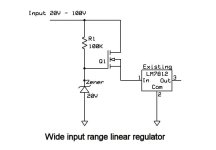
The limitation is usually in the voltage regulator part of the controller. Fixed resistors to drop the voltage won't have a very wide input range. A linear pre-regulator would be much better. Most chinese controllers could be modified to work from about 15v to the maximum rating of the FETs/caps (60 - 100V).

Below is a circuit I've used on several projects. This would take the place of the power resistors feeding the 7812 regulator in the controller. Q1 is almost any FET with enough voltage and current rating. I used a FQP6N40C in the Zephyr circuit. These can handle up to 400V.

Depending on your maximum voltage, the FET may get pretty hot and need a heat sink.

The same circuit can be used with a Darlington NPN transistor, but R1 will need to be lower, like 15K and will tend to run hotter.
Wide input range linear regulator.jpg
 
Would this circuit work? I'm trying to keep it simple but when the batteries are connected in the two parallel diodes fitted for series are still connected.

Untitled-5.jpg


Untitled-4.jpg
 
fechter said:
It's certainly possible to make a controller that will work over that kind of voltage range.

The limitation is usually in the voltage regulator part of the controller. Fixed resistors to drop the voltage won't have a very wide input range. A linear pre-regulator would be much better. Most chinese controllers could be modified to work from about 15v to the maximum rating of the FETs/caps (60 - 100V).

Below is a circuit I've used on several projects. This would take the place of the power resistors feeding the 7812 regulator in the controller. Q1 is almost any FET with enough voltage and current rating. I used a FQP6N40C in the Zephyr circuit. These can handle up to 400V.

Depending on your maximum voltage, the FET may get pretty hot and need a heat sink.

The same circuit can be used with a Darlington NPN transistor, but R1 will need to be lower, like 15K and will tend to run hotter.


wowowowow, this is a neat circuit. just read this, but was helping the guy who blew up his controller and could not figure out what i was seeing on his pcb. i am gonna go link this to his thread because i can see this is just what they did for the input on his controller. thanks
 
alsmith said:
Would this circuit work? I'm trying to keep it simple but when the batteries are connected in the two parallel diodes fitted for series are still connected.

S--D.jpg


P--D-1.jpg

I cant help but think none of the diodes are needed, surely this method of change over does not need them?
 
You would only need the diodes if the batteries have an integrated BMS with active cutoff. Even then, you would only need the diodes across the batteries.
 
fechter said:
You would only need the diodes if the batteries have an integrated BMS with active cutoff. Even then, you would only need the diodes across the batteries.

Yes, each battery has their own BMS. Thanks!
 
Looks good.

Again, the reason for the diode is if the packs are in series and only one BMS trips, the voltage across the BMS would be double what it was designed for and could cause failure. With more packs in series, this becomes more of an issue. If the FETs in the BMS are rated for more than the combined series voltage, you don't need the diodes.
 
Hello all :)
is this schematical working correctly ?
i should be interested fo rmy own (2x48v / 15Ah vs 1x96v 8,5Ah with a Lyen controller)
Regards
 
chilledoutuk said:
The question is what is the max current handling switch available to do this?

That's something I've been thinking about for a little bit. You really don't want to switch under load, so there isn't an arc to have to quench, so the voltage rating of the contacts shouldn't matter.

Finding DT relays rated for that sort of current is a pain, though, so I wonder if you could get away with using a few of those small 10a DPDT 12v relays ganged in parallel. It should work for smaller setups, but it doesn't exactly scale elegantly to Lyen 100v 100a controller. If they're rated for switching at 10a, what do you think they can take if they're only switched without a load?

A reversing contactor would be rated for the current and might work if you can sever one of the internal connections and run a lead to it. Otherwise you'll set yourself up for a spectacular dead short. Consider that awfully risky.

You could make your own knife switch for the Doc Brown look, but that might be a poor fit for handlebar mounting. :mrgreen:

There's always the option to make a connector block of Andersons to swap between series/parallel. A few others have done it for charging. You wouldn't have any current issues then, but you'd have to physically unplug one thing and plug in another. It really looses out on elegance, though. I think the ideal would be a handlebar-mounted switch that you could just flick at a stop light or before letting a guest try out your bike.

Couldn't this be done with a couple of appropriately-specc'd FETs? What might that circuit look like?
 
Back
Top