Timing Adjustment Tool

Yep,
It should be able to work with any sensored hub motor.
Will be interesting to see what performance increase we can extract from hub motors by fine tuning the timing parameters.

Because hub motors are optimised to run in only one direction, the default timing on them is likely offset from neutral to be slightly advanced. This may mean there is scope to improve the low speed torque of these motors by retarding the timing at low speeds.

Advancing the timing at high speeds should still give us some increase in RPM that we have already seen demonstrated on the RC motors.

Looking forward to trying this one out on the MAC and MXUS hubs.

Burtie
 
I found a bit of time to test the TA with a sensored Astro 3220, switching between Delta and Wye to see if I could correct for the required timing shift between these two modes.

Here is how it went: ( warning: --- this is extremely nerdy, viewing this may give you a nose-bleed :shock: )

http://www.youtube.com/watch?v=YGT6_p0WkvE
[youtube]YGT6_p0WkvE[/youtube]


Burtie.
 
Hero status for Burtie.
 
that is so good burtie,

for a couple of years now this timing issue has been the hold up to getting big rc type motors (or any brushless really) to run properly
and efficiently to high rpm.

its been so hit and miss with the timing of various combinations of controller, motor, wye/delta and hall positions, and the fact that at anything at higher rpm then requires a further amount of advance that you may not know about and cannot really change..

more recently ive gained an understanding of the situation, and it seems that once you have a good startup (around 0 deg) timing setting sorted, the major
problem is the delay in the controller, theres a fixed time lag between getting a hall signal and driving the phases, at low rpm you wont notice but as the
revs get up above 1000 or so it starts to fall behind because theres less time between cycles, and at 5000+ you start hitting a wall of increasing current/heat
and that harsh sound from the motor -you need more advance.
this is beside the further changes like wye/delta that require another timing setting.

there seemed to be no good solution to this problem, so our best shot at light and powerful e-vehicles just give us headaches -until burtie, a superhero,
trapped in a nerds body steps in and saves us all.. :D
 
Ok Toolman2 and I just set this up with my Colossus motor.

Prior to using the timing adjuster we were getting a max 4700rpm approx jumping to over 50amps draw. Obviously we had some issues with the neutral timing or the sensor positions.

NOW we run it with the timing adjuster....
Max RPM: 6030
Volts: 76volts (same as before)
Max current: 5.5 amps
No load Power: 240 watts

Man this sings!!!

[youtube]rUwjLzmNWR0[/youtube]

Bertie the settings are:
Static : -12
Dynamic: -6
Ref RPM: 1000

Comments... brilliant!!!
However can we loose the - before the values? you know making +ve numbers advance.

Thanks
 
Awesome :)Awesome :)Awesome :)Awesome :)Awesome :)Awesome :)Awesome :)Awesome :)Awesome :)Awesome :)Awesome :)Awesome :)Awesome :)Awesome :)Awesome :)Awesome :)Awesome :)Awesome :)

Ok so I have not read the whole thread carefully but lfp says a throttle based imput but a current based map vs rpm is what will likely work better.
I think of it like this on a car with efi tps vs rpm is alpha N and manifold presure vs rpm is MAP based. Map based is more acurate (te load changes for hills ect and its the load on the engine that matters for setting timing at a given rpm) Now the current is a far better way to adjust the timing at a given rpm because as the load goes up or down you might move the trottle but as the engine heats up you will also aply more throttle ect.

Anyways very cool I want one how much and were do I paypal?
 
SplinterOz and Toolman2,

Fantastic work guys! Good to see that monster motor spinning up sweetly :D


Arlo, interesting analogy with an ICE. I will try to play with current sensing on a future version to see what benefits we can get.

Meanwhile I need to try some testing with a real mechanical load (when it stops raining for long enough) to make sure everything is still ok.
Assuming it is, I will then throw some more money at this thing and get a batch of PCBs made so I can reproduce them easily and offer them for sale to ES members. Currently they just take too long to make by hand :?

So keep an eye on the for-sale section if you want one, hopfully it wont be too long now!
 
SplinterOz said:
Ok Toolman2 and I just set this up with my Colossus motor.

Prior to using the timing adjuster we were getting a max 4700rpm approx jumping to over 50amps draw. Obviously we had some issues with the neutral timing or the sensor positions.

NOW we run it with the timing adjuster....
Max RPM: 6030
Volts: 76volts (same as before)
Max current: 5.5 amps
No load Power: 240 watts

Man this sings!!!

[youtube]rUwjLzmNWR0[/youtube]

Bertie the settings are:
Static : -12
Dynamic: -6
Ref RPM: 1000

Comments... brilliant!!!
However can we loose the - before the values? you know making +ve numbers advance.

Thanks


YES!!!!!!!!!!!!

I knew that monster wouldn't have such absurd no-load current with the right timing!

This is fantastic!!!

Hooray!!

Burtie = Hero!!
 
Hi Nick,

Yes I think I probably do :)
I have been looking for an excuse to learn to use a schematic and pcb design tool for a while now and have found one that looks promising, called 'Kicad' .

I thought I would layout the board and send the design to some online PCB manufacturer to get a batch of 100 or so made up.

Any tips or suggestions you have to ease the learning curve would be very welcome !
 
Burtie,

I'm in Wincanton, not too far away. If you want to come up to the office/lab one day, I'll show you the whole routine and how to link things up. I work with Protel but the principles of these packages are all much the same.

If you do it right, its brilliant, because all the paperwork gets done automatically, all the automatic checking falls into place, and the chances of getting a working product first time are really high.

Same offer to Jeremy.

Nick
 
Yup just read the whole thread! Burtie=hero!!!! :idea:
 
Cheers Arlo! (insert hero smiley here)


Nick,
Thanks for the offer I would like to take a visit some time. First though, I want to try learning a bit about these pcb design tools
so that I can try and ask some intelligent questions when I get there!
 
I couldn't wait any longer, it was time to do some real load testing with this Timing Adjuster thing.

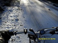
What better time to do it than when the lanes have a beautifully polished icy layer covered by some soft fluffy overnight snow :D


I programmed a mild adjustment profile into the device, wired it in, put it in a plastic bag and strapped it to the side of my bike.

View attachment 1


I did a few doughnuts in the driveway to gain some confidence, and set off.

Icy road.jpg


I managed to find a few places where the snow was deep enough for the tyres to get some grip so that I could try some decent acceleration runs... pulling nearly 4Kw with my Turnigy 80-100.

The good news is that it all seemed to work fine, no stutters or hiccups or controller fires, -No drama :D :D


The bad news is that I am afraid I did not record any performance comparison figures, the ice was just a bit too scary :shock:


Burtie
 
Burtie said:
The bad news is that I am afraid I did not record any performance comparison figures, the ice was just a bit too scary

Shame, shame. Now you go right back out there and kill yourself all proper now! :twisted:
 
I love the snow and ice on bicycles! One day i was riding to work on my peddle powered bmx and tried a 360 at top speed in front of the bodyshop i was going to and one of the guys came out side so see me slide past the shop backwards he was so lost he shook his head and forgot why he came out and just went back inside!
 
Mr burtie.
Are you using outrunners? I am asking because I think you have them next to conductive metal and I think that creats an eddy brake... Or does it change because of the iron ring around the out side of the magnets??????
I have been looking at how I want to mount my outrunner and was afraid of having it next to the frame!
 
There is about a 1cm gap between the rotating can and the metal frame, I guess there may be some eddy currents generated there, but they cant be that significant because the frame never seems to get warm.
Only the faceplate gets hot, where it conducts heat directly from the motor.
 
This is looking really good, Burtie, excellent to see it working "live".

I'm guessing that the board you're using is this one: http://www.skpang.co.uk/catalog/product_info.php?cPath=33_132&products_id=299 It looks as if this could be just bolted on to the basic BLDC controller hardware I've got working to make a pretty versatile programmable controller. The hardware motor drive is bog simple and foolproof, driven directly by the Hall states fed into it, and with excellent hardware driven high-speed current limiting on the fly. With the addition of your speed-dependent timing advance, and, I suspect, the ability to add additional programmable functionality fairly easily (I'm guessing that you're only using a small part of the capability of that board) then this could form the basis of a pretty tough and versatile controller.

Jeremy
 
I wondered if this: http://www.skpang.co.uk/catalog/product_info.php?cPath=33_164&products_id=474 or similar 32 bit module would be a good host for an integrated timing and motor controller brain. It would be an interesting next step to integrate the two functions.
There would probably enough spare processing capability to provide data logging functions similar to what we see now on the high end RC ESCs.

Great job on your controller project BTW. You seem to have it working well enough without using any micro controllers!
Jeremys BLDC controller: http://endless-sphere.com/forums/viewtopic.php?f=2&t=23350
 
Great work Burtie! I've always wanted to see what something like that would do.

Now if it could just be integrated into the motor controller. :wink:

I thought of mounting the halls intentionally way advanced and using a variable time delay to get the desired timing. The time delay would be a function of rpm.
Anyway, you figured out how to do all that, which is great.
The mapping idea is good too. Once you figure out the optimum timing for every operating conditon (rpm, load) it can be put into a lookup table like many car engine computers.
 
Burite,

I have been thinking about the throttle input load type arrangement people have talked about, as in if minor throttle then reduce the advance.
You already have a static advance value in your current design, IF you use that as the "most" advanced and then use the throttle input to vary that value you may have a simple way to include the input without going to advanced mappings.

That is if it is proved to be required.
 
Back
Top