• Howdy! we're looking for donations to finish custom knowledgebase software for this forum. Please see our Funding drive thread

Troubleshooting 48V 25ah lifepo4

Joined
Jun 3, 2012
Messages
55
Location
Whidbey Island, WA
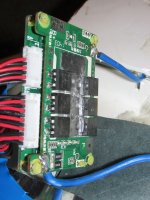
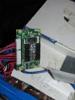
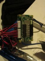
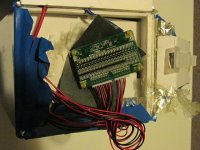
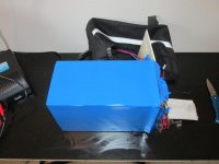
Purchased this from Golden Motor USA on ebay, and have been pretty happy with it putting over 1200 miles on my KMX. It has gotten me to and from work without having to charge at work - 40 miles round trip with some serious hills! Sadly it decided to stop accepting a charge yesterday. Tried two different chargers (48V), both displaying red and green leds which I usually get when the battery reaches 57V. Currently measures 47.3V with a multimeter. Removed plastic wrap on the front to expose the BMS and measured the following voltages:

1. 3.58V
2. 3.58V
3. 3.58V
4. 3.56V
5. 3.58V
6. (multimeter all over the place between 6.5V and 0V)
7. 3.58V
8. 3.58V

Possible bad cell on #6, or could a faulty component(s) on the BMS cause this?

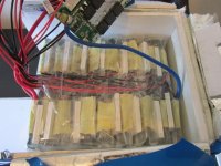
IMG_0004.JPG
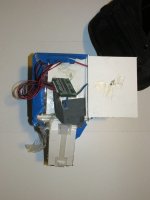
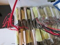
IMG_0006.JPG
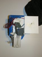
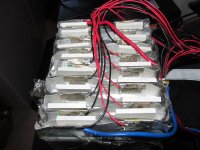
IMG_0014.JPG
 
bachmaninoff said:
6. (multimeter all over the place between 6.5V and 0V)
I'd guess either meter is not making a good connection (probe tip can't touch pin) or cell is not well-connected to that pin.

Hmmm. 47.3V divided by 8 cells (all you have listed) is almost 6V per cell. What chemistry are they, becuase I don't know of any with that voltage per cell?

Or is that not all the cells in the pack?

I can't see any of the images because tehy're blocked by the provider of the wifi I'm using. :(

If you attach them to your post here on ES I could see them.
 
Not really happy with the soldering on those points, so tomorrow I'll probably check the connections and re-wet those points of necessary... Looks like some other points could use that too.

15655005068
 
Well, I can't see the image cuz it isn't directly attached to your post, but it's much morelikely to be a loose/broken wire (inside insulation or at the crimp or battery end) problem than the solder joint, unless it's really obvious it's cold solder or no solder.
 
The red and black balance wires are confusing you. Measure cell voltages on all adjacent wires (wire 1&2, 2&3, 3&4 etc) , not just between the red/black pairs.

And you want to inspect where the balance wires are attached to the cells for a solid connection there.
 
Yeah, 16 cells. 17 wires, one is the -, and all the rest are the + of each cell. As you go down the row, each cells + is also the next cells -. So hop down the row, carefully, and check the voltage of each cell.

A bad connection anywhere on those red black wires, or in the plug, could cause the pack to shut off and not discharge, by fooling the bms that that cell is at 0v. That bad connection could be where the wire solders to the cells, so if you find a bad one, you might have to unwrap the top of the pack to fix that.

In addition, the reason all chargers show finished when you plug them in, could be a fault in the charger plug or the wires leading into the pack.

Charger green is either finished, or it's disconnected. So look at that too. Two problems at once is quite possible.
 
you did not say how many Ah you bot here.

the black wire on the far left is the bottom of the #1 cell, and the red wire next to it is the top of #1, but also the bottom of #2 and the third wire, the next black one, is the top of #2, and bottom of #3 and so on up to the top of #16. where it goes from one plug to the next it still follows the same sequence and you measure from that top black one over to the black one on the next plug for cell #11.

post up the measurements, if you can measure while it is charging and is fully charged so the green light turns on then we can tell if the BMS is working.

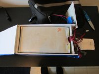
to see the pouches, you can cut the blue shrink wrap with scissors along the middle of the side above where all those sense wires go under. cut from one end to the other end and remove it. you can tape it back down later.

that will expose the tops of the pouches where the sense wires are soldered to the pouches. that is where it is most likely you have a bad connection.
 
Wow thanks for all the help!

I have measured cells 1-16 (haha can't believe I missed half of them!) as follows (plugged into charger with charger showing green and red LEDs) :

1. 3.67V
2. 3.59V
3. 3.68V
4. 3.59V
5. 3.63V
6. 3.62V
7. 3.61V
8. 3.60V
9. 3.61V
10. 3.61V
11. ??? unable to get a solid reading
12. ??? unable to get a solid reading
13. 3.57V
14. 3.56V
15. 3.58V
16. 3.61V

And finally when I measure from the #1 to #16 on the bms I measure 57.5V!!! So all the cells appear to be working, though out of balance. For #11 I'm going to re-wet that joint where I'm measuring it at on the board. Though at the plug, I'm still measuring 47.5V...
 

Attachments

  • IMG_0017-001.JPG
    IMG_0017-001.JPG
    40.3 KB · Views: 3,545
Hey Gregory thanks for the help with those photos!

dogman dan said:
A bad connection anywhere on those red black wires, or in the plug, could cause the pack to shut off and not discharge, by fooling the bms that that cell is at 0v. That bad connection could be where the wire solders to the cells, so if you find a bad one, you might have to unwrap the top of the pack to fix that.
dnmun said:
to see the pouches, you can cut the blue shrink wrap with scissors along the middle of the side above where all those sense wires go under. cut from one end to the other end and remove it. you can tape it back down later.

that will expose the tops of the pouches where the sense wires are soldered to the pouches. that is where it is most likely you have a bad connection.

Ok, looks like I'm going here next... Will post results in a while.
 
Ok, did some multimeter readings on the pouch tabs themselves before I solder the wire back to the tab... Cell 12 measures 3.61V, and cell 11 measures 3.83V... Commencing research on lifepo4 pouch tolerance.

IMG_0025.JPG


Looking at:

https://www.endless-sphere.com/forums/viewtopic.php?f=14&t=55103

Maybe I'm ok... But the fact that one of these cells got to 3.83V, should I consider buying a new BMS?
 
Ok I soldered the loose wire back onto the tab. Now I can measure all the voltages individually from the BMS, and still getting 57V+ across all cells. However I'm measuring 47.5V both at the plug and the BMS output. I guess I have a faulty BMS?

Edit:

Let it sit for a while, now its reading 57V at the output, and cell 12 is 3.56 and cell 11 is 3.57! Whew! BMS is working...
 
why did those cells drop in voltage while it was charging? did you solder the wire back onto the pouch already and did you put it on the right pouch. no pictures of the pouch where the sense wire disconnected. i would like to see all of those soldered tabs. every one.

we can show you how to test the BMS but first we need to get your pack balanced.

i suspect this is what happened to the other guy who was whining about sunthing guy. most probably the other guy who sent his back too.
 
dnmun said:
why did those cells drop in voltage while it was charging?

I was wondering the same thing... Did re-connecting the sense wire have an effect on this maybe?

dnmun said:
did you solder the wire back onto the pouch already and did you put it on the right pouch. no pictures of the pouch where the sense wire disconnected.

I did solder the sense wire back on the tab and I'm assuming it was the correct tab since my bike works now.

dnmun said:
i would like to see all of those soldered tabs. every one.

we can show you how to test the BMS but first we need to get your pack balanced.

Sounds great - I appreciate your help! First thing tomorrow I'll take the pack back down to parade rest...
 
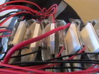
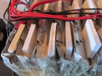
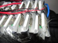
can you take close up pictures from the side of the tabs so we can see the cross section of how it is crimped and where the copper tab meets the nickel tab of the next one. the tabs are clamped together by a spring clamp there?
 
The charger LED1 may look green in the photo, but its switching back and forth between amber and green. I put on 1.5ah yesterday just having the cycle illuminator, CA, rear light and LED whip turned on, and did a quick throttle check too. Let me know if you need a different angle on these photos...

View attachment 5
IMG_0034-001.JPG
IMG_0035-001.JPG
IMG_0036-001.JPG
IMG_0037-001.JPG
IMG_0038-001.JPG
 
Pack has been on the charger for a few hours now and I haven't seen LED1 turn amber for a while... Voltages (while plugged in) are as follows:

1. 3.56
2. 3.54
3. 3.56
4. 3.55
5. 3.56
6. 3.56
7. 3.55
8. 3.56
9. 3.56
10. 3.56
11. 3.56
12. 3.54
13. 3.56
14. 3.56
15. 3.58
16. 3.56

So - standing by for recommendations... Looks like +/- .02 VDC variance. Are these measurements good enough for government work, or should it be balanced further prior to using it for commuting?
 
sorry busy all day yesterday but those look like the voltages right after it was taken off the charger so it is close to charged up. you can even raise the charger voltage a little to get it over 3.60/3.61V while charging. i expect the BMS has a 3.60V balancing voltage.

the complaint the other guy made was that the tabs are just folded over on each other and have no physical/electrical connection at the tabs so he said his pack was failing because it would not make the connection between cells and so it would not work.

i can make out two different widths of metal so i assume one is the nickel part that is crimped with the knurling tool onto the aluminum tab of the anode.

he said he saw a spark, which implies a bad connection, but he would never expose this much of the battery, in fact did nothing to help.

so let us know if you can see or feel loose connection where the tabs are folded and the ultimate test is to use a big dummy load and discharge the battery into the load and then use your fingers to feel each of the tabs to see if any of them get hot to the touch.

but looking at it and seeing two different widths of the tabs, i am fairly sure they are soldered together at the tabs, inside the fold, or maybe they are knurled together inside the fold. the sense wire is then soldered to the copper part and should be soldered to the nickel part of the tab on the top of #16.

i think that guy just had a loose sense wire like you had, in fact i suspect both of them had that problem.

the sense wires are subject to mechanical tension because they are not hot glued to something to prevent them from moving so i suspect this could be a common problem for this large battery. you may have to do this again, and again.

because of this, it might be a good idea to rig up a jumper across the BMS. if the BMS cuts off when a sense wire pulls loose, then you could have a jumper wire with male and female connectors across the BMS from the P- spot to the B- spot.

then if the BMS cuts out for no reason when it is charged, you could jumper across the BMS until you could repair the broken sense wire. this may be excessive, but it may be something to worry about later.

you may wanna put a piece of tape across the top of the tabs to hold those insulating foam shields in place. but i doubt is they will short since the pouches appear to be fairly thick. which is to be expected for a 25Ah pouch.

thanks for taking the time to do all this. but i think you kinda know what to expect now. figure out how to get some hardboard endplates on the ends of the pack and then put the pack into compression to make it last longer. you can leave the foam on the end or remove it for the hardboard endplates. the foam is just useless along with the shrink wrap for actually insuring longer cycle life.

then mount the BMS on the outside of that, you can hold the BMS in place on the some surface or other that you find works just by taping down the B- wire and the P- wire too so the BMS cannot move. you can also solder a different set of wires onto the BMS for charging and if you wanna add a switch i can show you where to add a switch in the BMS circuit current to turn the battery on and off. don't wrap the tape across the top of the mosfets because they may get hot.
 
Thanks so much for the pictures. Very interesting how the tabs connect. If not soldered, they would be more vulnerable to one pack in a paralleled group having a poor contact, and then the pack would have low capacity. Much like the popped spot welds on the cheap round cell lifepo4 packs used to be.

One thing I liked about the pings I owned years ago was the very solidly soldered connections at the tabs, to a pcb, and the glued down sense wires, so none could wiggle enough to break the wire at the solder point.
 
ping used hot glue to hold the sense wires down too. then later used that piece of hard plastic and glued the sense wire to that.

this big 25Ah pack is different from the other packs that sunthing guy makes too. just a huge form factor for a single pouch imo.
 
dnmun said:
sorry busy all day yesterday but those look like the voltages right after it was taken off the charger so it is close to charged up. you can even raise the charger voltage a little to get it over 3.60/3.61V while charging. i expect the BMS has a 3.60V balancing voltage.

Ok, I'm going to assume there's a pot in the charger to do this... Looking forward to taking it apart!

dnmun said:
so let us know if you can see or feel loose connection where the tabs are folded and the ultimate test is to use a big dummy load and discharge the battery into the load and then use your fingers to feel each of the tabs to see if any of them get hot to the touch.

Will do, when I was feeling them before they felt pretty solid.

dnmun said:
figure out how to get some hardboard endplates on the ends of the pack and then put the pack into compression to make it last longer.

Definitely! Thanks dnmun for all your help and suggestions!
 
you did good. too bad those other guys wimped out because we coulda helped them too.

it will be useful to see if this pack has greater longevity because it is a single pouch versus the others built by soldering multiple small pouches in parallel.

use a wattmeter, you can buy the cheap RC group wattmeter on ebay for cheap.

http://www.ebay.com/itm/GT-Power-RC-130A-LCD-Battery-Balance-Watt-Meter-Meter-Power-Analyzer-RSUS-/191010954651?hash=item2c7923dd9b

show a picture of your charger, it will have the screws under the rubber pads for feet. i think you have the Vpower charger which is not straightforward to hack up in voltage but we don't know yet if you have to.
 
Back
Top