uggh! another noob needs help :-)

Joined
Nov 11, 2015
Messages
12
Location
Rochester, NY
Hi I have been reading the forums on this site for about 2 months while attempting to build my first bike. please excuse me if I have missed one of the posts that already addresses my problem but I have yet to find answers to my problems.
I built my battery pack over the past 6 weeks from recovered LG 18650 cells from Dell Laptops. Design is 13s10p (quite a long process to test each battery and package equal voltage and capacity cell/banks.) in the end I have the battery completely built and it has 25.6ah per parallel bank (all parallel banks were built to have capacity within 0019Mah of each other). no batteries with less than 2300Mah were used and my max capacity on a few batteries was 2800Mah. I used braided copper for all parallel and series connections, and connected a 48v 13s BMS from China
Specs:
Operating Temperature: -20℃-70℃
Dissipation Power: less than 20uA
Brand Name:ANN
Supply Voltage:48V
Model Number: 13S48V40A
Type:13S 48V Batteries Protection Board
Application:13S 48V 1000W-2500W li-ion battery
Application:3.7V lithium ion battery
Continuous Working Current:40A
Max discharge protection current:100A
With balance function:Yes
Size:L110*W85*H15mm (4.33” X 3.34” X .6”)
Product Description 48V 40A BMS, 13S 48V(54.6V) li-ion battery protection board, 40A continuous 100A peak discharge

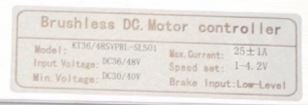
I used 10Ga silicone wire for my leads to the controller and charger and XT60 bullet connectors. When fully charged the battery reads 54.5v, I don't believe there is any problem with my battery, BUT the hub motor kit I purchased from Hallomotor (48v 1500w 29" Rear Wheel Ebike Conversion Kit with Sine Wave Controller+LCD) is not working correctly.
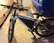
PROBLEM: When connected to the bike and I press the thumb throttle I get a short less than a second blip from the motor then it cuts out. press the thumb throttle again and the same thing less than 1 second and the motor quits. if I lift the rear tire off the ground and hit the thumb throttle it spins up as desired and hits 46MPH drawing 10.6amps max and a 2.7v sag down to 51.8v. as soon as I place the wheel on the ground and hit the throttle I get the short pulse and the motor quits. when I tried to ride the bike and use the PAS I get the exact same result a brief pulse of power from the motor and it quits. So the Thumb throttle and the PAS are acting the same. I have tested the Phase wires to the motor and get cogging when I short any 2 wires together. I have tested the hall wires for variable voltage when manually spinning the wheel all three show variable voltages. The throttle is showing good voltage, ground and varies voltage when turned. I have been contacting the manufacturer for support for 2 weeks and they are in china so each email takes 2 days to get help which has been minimal so far. They say I have a battery or controller problem. All of the testing I have done is a result of reading these forums and I feel I have exhausted all of the tests I can think of to get this up and running. Do any of you with years of Ebike experience have any ideas what my problem is. I am ready to get ebay involved and ship the whole kit back to China and request a refund. ANY help or advice is greatly appreciated, Frustrated in Rochester NY!
 

Attachments

  • EBike.JPG
    EBike.JPG
    71.4 KB · Views: 2,294
The described behavior and +10A no load current sounds like a Phase power - Hall sensor timing problem.

Could be a bad controller? Did you test the MosFETs inside the controller?

http://www.ebikes.ca/learn/troubleshooting.html

I don't trust the description of the battery pack either...
 
I did not test the mosFETs in the controller yet, I don't know the process to test the mosFETs. This is a new kit and I was hoping I would not have to crack open the controller, if I have to return the whole kit for a refund I don't want to void any warranty by doing so.

what do you mean by not trusting the battery, any further detail I can provide or can you shed more light on the no trust statement?

I will review your troubleshooting link, and thank you for your help.
 
Laptop cells don’t impress me for C rate and these being used ones to boot.

Did you test and verify how much current your completed pack is able to deliver? A kit like that needs a battery that can provide about 30A without sagging into LVC.

Anyway, probably not the issue since you’re reporting 10.6A no load current draw. That and the described behavior is very indicative of a miss-timed Phase/Hall system.

Good luck returning to China for refund. Let us know how that goes!
 
The hard part with this is having a decent point of reference, in order to apply the process of elimination. I'm assuming you have already done back to square one (sounds like several times) to ensure there is no poor connections etc. I doubt this is the cause given it is working/not working under specific conditions.

You need to be able to swap out the battery, controller, motor etc piece by piece to work out which is throwing you off. Ideally you would have spares which you know work (which you probably don't given you haven't done this already), or an ability to test each piece (i.e. ebike tester etc). Frankly, I suspect it is a controller issue but the retailer will attempt to blame your battery given you built it/they didn't supply it.

Do you know anyone around you that have bits you can try? Is there any shops selling ebikes close (they will probably have spares they may allow you to borrow)? This is probably the easiest way to move forward.

YKicks comments revolve around building a battery itself can be problematic.

Chinese retailers are unlikely to be co operative with the idea of sending it back. Hopefully you have used Paypal. if you have, I would be checking the timing on when you bought it versus whether you are still in the timeframe for opening a case. If your in that timeframe, I would be considering opening a case as it's likely to cost you if you have to start replacing/sending things back.

Please use paragraphs. A salient point per paragraph makes it easier to understand the issues you are having and easier to help you with them.
 
Ykick I tested the mosFETs and they appear to test good according to the troubleshooting link you sent me. I have 9.85 green, 9.82 blue, 9.90 kOhms on the ground tests and infinite resistance on each for the positive test. thanks for the link I used that same page to test the throttle, and hall sensor connections last night.

as you suggest I will research how to test how much current my pack is able to deliver. .....off to banging my head against the brick wall

Lurkin thanks for the advice all connections have been checked and rechecked. I am not using the brakes, lights, or cruise function (has a loop plug on it). and there is a 3 pin red/white/black speed sensor connection that has nothing to connect to? does that sound right (see picture)

unfortunately there are no local ebike dealers in my area and you are correct this is my first build so I have no additional parts to swap in and out. My brother has a 48v bike and I will be getting some Anderson power connectors like he is using to test my battery on his rig. At least I will know if my battery build is good.

I will check on the timing, I did use Paypal, so you are suggesting I open a case before that window expires or I may be SOL.

seeing as the hub spins up with no load on it would you agree it is most likely not a motor problem? that is the most expensive component so if I do have to purchase another controller I can deal with that.
 
His bike is a set of reliable spare parts if its working :)

Can you put up photos of your controller? It's unlikely I'll know the answer, but others on here will probably have more of an idea once they know exactly what you have.

I would be looking to find a speed sensor though. I don't know how temperamental these are if they are denied a speed sensor input.
 
Ykick is talking about the phase/hall matching. All setups don't always plug color to color. At 10.5 amp draw no load is WRONG. At that load you would trip either the controller or the BMS. Since it restarts I would say the controller is protecting itself and shutting down under load.

You want to put the drive wheel in the air so you can switch wiring easily and see if it changes the amp draw. Only partial throttle at first to see if the wheel spins or not. If spins you want to see what the no load draw is, in most cases it should be under 3 amps lower foe DDs than geared motors.
There's a chart to find the right color combo but I don't have the link, since I never needed it. I did it the hard way before I read about it. Someone will post a link soon or maybe before I post this.

Dan
 
Lurkin here is a picture of the controller. and for what it is worth what is a speed sensor seeing as I don't have one?
 

Attachments

  • cont model.JPG
    cont model.JPG
    12.3 KB · Views: 2,240
Aroundqube thanks for the link. I will try switching phase wires around and testing tomorrow, (just to be confident before I go switching wires around) my wheel does spin in the right direction when I lift it off the ground at 46 MPH on the speedo. the problem is when I set the tire on the ground I get only brief pulses of motor turning for less than a second and it quits. PAS does the same thing.

Thanks to all who have helped advise me, I will continue tests tomorrow.
 
The key to this test is observe both voltage drop and current while slowly advancing throttle, while the drive wheel is in the air. Because-- there is a wiring combination called ' a false positive ' , resulting in forward operation at high current. With the wheel on the ground, current would spike so high as to cause the system to shut down. You may see battery voltage sag with the on the ground test. Gives you a clue as to which garden path to go down.
 
Just some random thoughts. No real tech help.

I was looking at what Hallomotor sells on ebay and at their website. They seem to know what they're about. Hard to believe that they would ship a motor and the more complex sine wave controller that used the wrong color wires. I would guess a bum controller before bad wires happens.

Maybe first see if your battery works on your brother's bike and vice versa. Good luck.
 
here is some data from the power analyzer
starting battery voltage = 53.75, power on at throttle causes .03a draw, LCD on causes .13a draw no sag on Battery voltage
positive and ground connection on hall sensor shows 4.38v

With the wheel lifted (0 friction) tests were completed at 10, 20, 30, 40, and WOT @ 47.2 MPH with starting battery voltage of 53.75v
10 MPH - pulls Amps peak = .65a, voltage min. = 53.35v, watts peak = 63.4w
20 MPH - pulls Amps peak = 1.57a, voltage min. = 53.26v, watts peak = 83.6w
30 MPH - pulls Amps peak = 2.6a, voltage min. = 52.89v, watts peak = 139.8w
40 MPH - pulls Amps peak = 3.64a, voltage min. = 52.67v, watts peak = 192.4w
47 MPH - pulls Amps peak = 5.59a, voltage min. = 52.52v, watts peak = 294.1w

Stall testing: placed my foot under the tire (minimal friction added) starting battery voltage at 53.59v
Test 1 - wheel pulse then stops - pulls Amps peak = 1.19a, voltage min. = 53.35v, watts peak = 63.3w
Test 2 - wheel pulse then stops - pulls Amps peak = .62a, voltage min. = 53.32v, watts peak = 33.2w
Test 3 - wheel pulse then stops - pulls Amps peak = .13a, voltage min. = 53.443v, watts peak = 6.9w

Per aroundqube's link to wiki "4 steps to right BLDC motor wiring" (https://endless-sphere.com/w/index.php/ ... less_Motor)

changed phase wires: Controller side Y to motor side G, Controller side G to motor side B, Controller side B to motor side Y
result = blew 5a fuse, blew 10a fuse, no wheel movement, 20a fuse got a pulse from the wheel and it stopped.
pulls Amps peak = 5.6a, voltage min. = 52.22v, watts peak = 295.0w

changed phase wires: Controller side Y to motor side Y, Controller side G to motor side B, Controller side B to motor side G
result = with 20a fuse, no wheel movement, got a pulse from the wheel and it stopped
pulls Amps peak = 32.7a, voltage min. = 50.73v, watts peak = 1720.0w (big wattage for no movement)

changed phase wires back to normal: Controller side Y to motor side Y, Controller side G to motor side G, Controller side B to motor side B
result = with 20a fuse, wheel spins as desired while no friction is applied, throttled up to 20MPH
pulls Amps peak = 1.6a, voltage min. = 53.16v, watts peak = 85.1w

With the wheel spinning in the correct direction and getting to speed (with no friction) and the high wattage and amp draw from changing phase wires, and blown small fuses I am reluctant/scared :oops: to continue changing phase wire connections. Does anyone see any anomalies with my testing results, sag that looks out of line for the draw, anything you can surmise or suggest as next step troubleshooting? thanks for taking the time to review my test results your help and advice is greatly appreciated.
 
I thought you said it was 10+amps. If it's only 3 than it might be the battery or the bMS but normally if a BMS trips it won't restart without a disconnect. 5.5 amp no load is still high for a DD.
You switched some phase and it was worse than that's not it.
If it runs no load have you tried to pedal it to as fast as you can and then apply the throttle.
Have you tried it without the PAS?
Where are you getting the 47mph, on a bike speedo or the display and are they calibrated?
Does it run slowly with a light load or just quits?
As posted try a different battery or bypass the BMS to see if it's the battery.
As for knowing what they are talking about, is the very few sellers that really do. Not saying they don't it's so many that sell stuff and have know idea what they do. BMS battery is one of them a few years ago. Ask any question and 99% of the time they had no clue or never returned you email.

Dan

Hi DAND214, thanks for your reply the 10+ amps reading was taken as a peak of multiple attempts to get the wheel to spin up with load Trying to actually ride and having the motor stall numerous times.

The test results I just posted included turning the power analyzer off and on between each test to provide more accurate results of each test.

Initially when this problem started I did not have a PAS connected, and I was getting the same immediate stall on minimal throttle while going 10mph by pedaling.

As a problem determination step I removed the battery discharge leg from the BMS and connected the controller direct to the pos/neg on the battery. This should take the BMS out of the equation as it would only be used for balancing on charge with no impact on the battery current. So with both the BMS inline using the negative discharge, or direct from the battery bypassing I get the same result.

After this I decided to install the PAS to see if it worked correctly as an alternate throttle and could get the wheel to work properly. Result was the same when I pedaled the bike I could feel a pulse from the wheel then it cuts out. from my limited knowledge it sounds like the throttle and PAS are acting the same and yielding the same result so I would have to assume they are not faulty.

The 47MPH is coming from the LCD panel that came with the kit I have set the LCD to 29" wheel, and set all the other controller configurations as the manual/mfr. said.

It does not run slowly it just quits, I hear a "ping" sound from the motor when I pedal or apply throttle can feel a slight motor pulse then nothing, when I pedal again or hit the throttle I get another ping/ pulse and it quits. when I applied minimum load to the wheel for my stall test results I simply put my foot under the tire while lifted in the air so maybe 5 to 10 lbs of pressure, (less that the weight of the bike sitting on the ground.)

while I wait for my Anderson connectors (to test my battery on my brothers bike) to arrive I will take apart my solar boat steal 2 of the AGM batteries out, add another 2 AGM in series and attempt a whole different battery for testing obviously these are 60lb batteries :shock: at least that will give me an alternate battery to see if I get the same results.

thanks for your advise, I truly appreciate it. TJ
 
You have what I call a false positive wiring combo...right direction but wrong config. Whichever is harder to swap, halls or phases, swap 2 (any 2 and only 2). Then go to the other set that's easier (halls if you swapped 2 phases or phases if you swapped 2 halls), and changing only 2 at a time try the other 5 possible combos with only short pulses of throttle. With only 5 remaining possible (the current one isn't correct, but try it if you want), it's easy to be methodical only changing to at a time. I like to use alligator clip jumper wires for swapping around (take care nothing shorts), because they can't pass high enough current to hurt anything and swapping wires is quick and simple even when relaxing and taking my time. My motors have 6 phases and 6 halls, so a 3 phase I could do blindfolded.

Hopefully the BMS or controller cutting out protected everything from the likely long throttle tries of before. The right combo will sound smoother on the start and will have a lower more appropriate no load speed and a quite low (probably 2A or less) no load current Those false positive wiring combos typically have a very advanced timing and spin the wheel faster than is correct with usually a noisy startup though newer sine wave cheapie controllers may be pretty quiet.

That should solve your problem as long as you have your BMS wired correctly to the homemade battery pack. From the sound of it when you tried with a load the incorrect wiring tried to draw too much current and tripped the BMS current limit.

Regarding 3 phase brushless motor wiring the thing to understand is that every phase combo has one valid hall combo, and every hall combo has one valid phase combo. 3 are valid forwards and 3 reverse. Every false positive I have seen is a reverse for that combo or halls and that combo of phases, which is why I said to make the 2 wire swap. Once that "clicks" for you as a straight forward logic/math problem, then wiring configs are never a source of anxiety. If anyone suggests trying the 36 total possible combos, ignore them.

Oh, one last thing. Look out for spinning pedals if you hit a reverse combo or false positive that's reverse. Freewheels are free when the motor runs backward.

Once you get a more appropriate no-load speed and current at WOT, if you still get cutouts, then to test that the controller and motor are working correctly simply bypass the BMS. If you still get cutouts, then maybe under load the battery pack is sagging below the low voltage cutoff of the controller.
 
John in CR, thanks for jumping in... I reviewed a lot of your posts and you mention the false positive often and provide similar instructions. could you please be a little more detailed in helping me right the "false positive" your instructions are vague to the novice (me) that is not knowledgeable about he technology. I mean no disrespect, I am just new to this and a little confused by the
Whichever is harder to swap, halls or phases, swap 2 (any 2 and only 2).
Then Test? and record results for correct wheel direction? and voltage, voltage min, amps peak?
Then go to the other set that's easier (halls if you swapped 2 phases or phases if you swapped 2 halls), and changing only 2 at a time try the other 5 possible combos with only short pulses of throttle.
OK, so say I swapped 2 sensor wires above in step 1 cause they are harder to swap than the phase wires now I need to swap any two of the phase wires. Now Test? and record results for correct wheel direction? and voltage, voltage min, amps peak? or should I only be testing after swapping both step 1 and step 2 (no tests after the sensor wire swap?) I can record, document and test each combo, I just want to make certain I am doing it right. Man do I wish I could do this blindfolded, props to you for knowing your stuff.

Today I was able to get 4 - 12v AGM batteries charged up and connected in series I have not done exact testing to post yet, but with a different battery (bank) with no BMS inline I retested the minimal load on the wheel with my foot under it and it still pulses and stops. Tuesday I will post more detailed test results with current and voltage sag readings. I am leaning towards it not being the BMS or my Lithium battery seeing as I get the same result with 4 marine grade AGMs.

Big thanks to all of you that have provided advice, TJ
 
When testing wire combos use light or little throttle. Don't full twist if no response don't full throttle if no response.
Put a light bulb for load. I have use a blow dryer, but don't know it's proper to use. Checking to see if bms shuts down or if battery can take a load.
 
TJ,

By false positive I mean a wiring combo that spins the motor but isn't correct. The higher than expected speed and high no-load current are symptoms of a false positive. Your no-load current times the voltage means it's taking about 500W just to spin the motor and wheel, which clearly isn't correct. Since your false positive is forward, the valid combo leaving either the phases static or the halls static will be one of the 3 reverses, so not only do you need to find a good combo, but you need to change direction.

You have 2 sets of wires, the 3 thicker phase wires is one set and the 3 hall wires (not including the gnd and +5V hall supply). One of the sets is typically harder to swap around, so choose that one to swap 2 wires and then remain static. After you swap the 2, you can give the throttle a quick pulse to check if you want, but I don't believe going from a false positive right direction can be corrected with just a 2 wire swap. There's nothing wrong with giving it a try after the initial 2 wire swap to satisfy yourself as well as to ensure that you've tried all 6 possible combos of the other set that you're going to swap around.

No need to write results down as the correct combo will be obvious. The easiest way that I've found to be systematic is chose one wire as your anchor, eg motor yellow phase wire. Only swap around 2 wires at a time. First with yellow on yellow try the other 2 (BB with GG, and BG with GB). Then move yellow motor to controller blue, and try that and then swap the motor B and G again and try. Then move motor yellow to green and try. Then swap B and G again. That covers all 6 possible, and you will have found the valid combo in there. Once you prove that valid really is good by looking at no-load amps.

Then you should be ready for a quick test ride, and if all is good mark the proper wiring combo, so you don't have to hunt for the correct sequence again with that motor/controller combo. I keep all 3 colors of electrical tape and shrink, and since a controller change is more likely than a motor change, I mark the new colors on the controller side of the connectors to make them match the motor.
 
John in CR, thanks you for your clarification and guidance. I will test the various combos tonight and see if I can right the timing. Hallomotor is finally going to ship me a replacement controller so in 2-3 weeks I should be able to swap that out and see if the new controller works. In the mean time I will continue with your advise to see if I can make it work correctly.

For my knowledge and future reference you say there are 6 combinations on the phase wires.
1. correct direction, quiet, handles load without stalling, and should pull low amp draw
2. reverse direction, quiet, handles load without stalling, and should pull low amp draw
3-6. direction varies or no movement, loud, stalls with or without load, and should pull higher amp draw.

The test sheet I started to follow when trying this the first time referenced using a 5amp fuse, I smoked a 5 and 10 amp fuse when I tried 2 different combos last time and the next smallest I had was a 25a fuse. should I go buy a bunch of 5a fuses for this and plan on smoking a few for the wrong combos? or is it ok to test combos with a 25a fuse? I may have tried more than small throttle increases the first time when the motor did not spin at all. I will only make minimal throttle advances fro these combo tests.

Thanks again for helping me troubleshoot, you have contributed to my understanding greatly :D, TJ
 
Guess who tried to test the suggested https://endless-sphere.com/w/index.php/ ... less_Motor - This guy

The guide says "crossbreaks hall sensor and phase wiring spreadsheet for tying most of the 36 possible combinations"

please tell me that there are actually more than 36? cause I tried them all and am ready for more :lol:

Of all testing 4 setups worked with low amperage and smoothly in the right direction, unfortunately I realize now that all 4 setups balance each other out to be the same as the correct controller to motor sensor and phase wires colors just in a different order -grrr.... unfortunately all 4 setups in the picture (attached) failed the load test and the motor still quits with load applied (A1, B3, C6, E5)

The positive thing is that in test F4 the motor ran smooth with no stutter in reverse but it continued to spin when a load was applied and had the lowest amp draw of all smooth correct direction setups. A glimmer of hope!

....and the down side is still not working in the correct direction with load. :evil: so is there more combinations to try? ...to the novice it makes me think I was almost there.

hooked up my lithium to my Bros bike and it worked perfect. plus the alternate AGM batteries I used for testing backup the possible battery problem. at least I feel good about exhausting that as a possible point of failure.

if anyone or John ion CR can review and advise I would greatly appreciate your expertise.

Thanks for all of you guys help, TJ
 

Attachments

  • Capture.JPG
    Capture.JPG
    191.7 KB · Views: 1,239
TJImagineer said:
Guess who tried to test the suggested https://endless-sphere.com/w/index.php/ ... less_Motor - This guy

The guide says "crossbreaks hall sensor and phase wiring spreadsheet for tying most of the 36 possible combinations"

please tell me that there are actually more than 36? cause I tried them all and am ready for more :lol:

Of all testing 4 setups worked with low amperage and smoothly in the right direction, unfortunately I realize now that all 4 setups balance each other out to be the same as the correct controller to motor sensor and phase wires colors just in a different order -grrr.... unfortunately all 4 setups in the picture (attached) failed the load test and the motor still quits with load applied (A1, B3, C6, E5)

The positive thing is that in test F4 the motor ran smooth with no stutter in reverse but it continued to spin when a load was applied and had the lowest amp draw of all smooth correct direction setups. A glimmer of hope!

....and the down side is still not working in the correct direction with load. :evil: so is there more combinations to try? ...to the novice it makes me think I was almost there.

hooked up my lithium to my Bros bike and it worked perfect. plus the alternate AGM batteries I used for testing backup the possible battery problem. at least I feel good about exhausting that as a possible point of failure.

if anyone or John ion CR can review and advise I would greatly appreciate your expertise.

Thanks for all of you guys help, TJ

That's the "hard" chart to me but if it worked, great. So if you’ve found a good Phase/Hall combo but turning wrong direction use the 1st chart called “4 steps to the right BLDC Motor wiring” lower portion describes how to reverse the motor.

https://endless-sphere.com/w/index.php/Determining_the_Wiring_for_a_Brushless_Motor
 
No use typing my name when I told you how to get to the same position in 5 tries, so I wasted my time before, and despite not listening and going the long ridiculous tree killing way that teaches nothing and typically comes up with the wrong answer, you came up with the wrong answer. There's no such thing as 4 valid combos and it sounds like your one valid is one of 3 reverses. I say tree killing due to unnecessary use of paper.

Low no-load current means at WOT (Wide Open Throttle). If the reverse works under load, then you are at the same position as before, swap just 2 of one set and find the right forward combo of the 5 remaining possibilities of the other set. Otherwise you have another problem.

Once you have a nice starting low no-load current at WOT in forward, if it still cuts out and you already proved your battery (including the BMS), then it's most likely a bad connection of the primary power wires (battery leads and phase wires). That could be in the connectors, the wires' connection to the connectors, or a poor solder solder joint anywhere in the main pathway...ie there is a connection but it doesn't allow high current to pass. An incorrect LVC setting could also cause the symptom and cut off when higher current pulls the battery voltage down, but my money would be on a bad connection which could also prevent you from finding the 6 valid combos (3 fwd & 3 rev)
 
Back
Top