Unstoppable Geared hub motor!

The Stig said:
The bike will definitely be full suspension, DH. And yeah I'm seeing that the electronic solution Could be the cheapest and simplest route, if the details work out.... Although the mechanical solution offers better performance.
CogHog said:
Cheapest route is electronic. Just put a micro switch on the rear suspension so when it is at full extension the motor is off. You are most of the time sitting on the bike or even the weight of the ebike alone may trip the switch on. Hard tail is another story.
y'all think this would work if I wired it so the micro switch to cut off the throttle? I wonder what type of controller and type of switch this would work best with?

Any controller, just inturupt the signal wire. And any microswitch with a NO connection. Id say itd be considerably more effective, since it has far less mechanical complexity.
 
In my experiences DD hubs are better suited for serious off road use, all this sounds good in theory but making systems more complex usually introduces more points of failure.
 
sn0wchyld said:
The Stig said:
The bike will definitely be full suspension, DH. And yeah I'm seeing that the electronic solution Could be the cheapest and simplest route, if the details work out.... Although the mechanical solution offers better performance.
CogHog said:
Cheapest route is electronic. Just put a micro switch on the rear suspension so when it is at full extension the motor is off. You are most of the time sitting on the bike or even the weight of the ebike alone may trip the switch on. Hard tail is another story.
y'all think this would work if I wired it so the micro switch to cut off the throttle? I wonder what type of controller and type of switch this would work best with?

Any controller, just inturupt the signal wire. And any microswitch with a NO connection. Id say itd be considerably more effective, since it has far less mechanical complexity.
The electronic solution in it's self will probably be more reliable! I feel like I need to look at the details of the e-solution a bit closer... need input from all the ES controller gurus :p

I'm just afraid the power cutting in and out will be jerking me a bit, as the throttle cuts in and out, while going over bumps. This all depends on how fast the controller can respond to the throttle signal -> then how fast the controller can increase the RPMS of the motor -> then how smoothly the controller increases the current once the motor RPMs have caught up with the tire RPMs. If the controller is at max current from before the motor RPMs reach the tire RPMs, and keeps pushing max current at once the freewheel clutch has engaged in the motor, then I'd expect this to jolt the bike and affect my stability.

Lyen MK1 Vs Lyen MK2 Vs Crystalyte Vs BMC controller, which would perform better in this system? controller mods?


As for mechanical, I still want to explore the half Leaf Spring idea. Not sure where to start looking for parts or how I design one.


shock said:
In my experiences DD hubs are better suited for serious off road use, all this sounds good in theory but making systems more complex usually introduces more points of failure.
I am considering a crystalyte HT35 or H40... but DD's are inherently bad for handling and stability because of the weight of the motor being unsprung weight.
This may be introducing a new point of failure but the whole point is removing a more critical point of failure by protecting the gears inside the hub.
As for mid drives, I wouldn't like the noise and I know a lot of people who would admire it the silence of hub motors... but I might consider a mid drive if there were hub gears that could fit in 170-175mm dropouts and it was cheap, 2000w+ and easy to instal with an extra wide Bottom Bracket.
 
The Stig said:
... but I might consider a mid drive if there were hub gears that could fit in 170-175mm dropouts and it was cheap, 2000w+ and easy to instal with an extra wide Bottom Bracket.

This is the only stoopid-wide gearhub I am aware of. But I would not trust it to accept 2000W without problems.

The only internal gears I would trust with 2000 watts, within their input torque limits, would be the Rohloff Speedhub 500/14 and the Fallbrook NuVinci N171. Anything else I reckon you'll break.

Derailleur gears don't break dramatically like gearhubs. They deteriorate quickly instead. You'll do that too, with 3hp into a system designed to tolerate 1/2hp. Same with the gears in a geared hub motor. The only kind of electric assist that tolerates large multiples of its design power is a direct drive hub motor.
 
Chalo said:
The Stig said:
... but I might consider a mid drive if there were hub gears that could fit in 170-175mm dropouts and it was cheap, 2000w+ and easy to instal with an extra wide Bottom Bracket.

This is the only stoopid-wide gearhub I am aware of. But I would not trust it to accept 2000W without problems.

That might work if it could take 1800w and last
 
The Stig said:
Chalo said:
The Stig said:
... but I might consider a mid drive if there were hub gears that could fit in 170-175mm dropouts and it was cheap, 2000w+ and easy to instal with an extra wide Bottom Bracket.

This is the only stoopid-wide gearhub I am aware of. But I would not trust it to accept 2000W without problems.

That might work if it could take 1800w and last

It's all a matter of input torque. Higher than normal speeds under load I think it would have no problem with.
 
So I had some new ideas about having a torsional spring to protect the gearmotor from shock loading. Inspired by the EVworkslab.com non-flat torque arm and Amberwolf's idea of using a leaf spring.

So I would have a torque arm spring cut in 304 stainless steel, in a similar shape to the non-flat EVW torque arm(see pics below).

The original EVW TAs are 5/16 thick A36 steel, and recommended for sub 2500W builds. He also reported some FEA results:
I did a quick check using 150N-m of torque.

Based on the results the stress at the edges of the axle were pretty low (.15x the yield)

Pic of EVW original TA:
EVW TA - Original.jpg


Pic of thinned EVW TA, a potential desing for a "leaf spring" torque arm:
EVW TA - Thinned.jpg


Now all this means that the axle will have to rotate inside the frame. So basically I will have a new set of greased bearings where my dropouts used to be.
My frame would now have 16mm round holes where the dropouts used to be, my motor axle has 14mm(major dia.) threads.
I will machine a collar to slip onto the threaded axle to pick up the radial loads. I will have washers on either side of the frame to allow the axle to twist. The whole thing will be packed with grease, and maybe shielded from the elements.

Heres a sort of exploded diagram of the bearing between the motor axle and frame(plus the torque arm spring, thing, allowing the axle to twist a bit):
769893d8-d28b-4baf-8048-0491bd135142.jpg


But how thin to make the leaf spring... The motor is an oil cooled MAC 12-turn at 72V and 30-40A.
Will I need to perform FEA? Or would 1/2 the thickness(as drawn in the second drawing) of the original TA work? or 1/3 or 1/4 the thickness...
 
BTW I saw a post on another thread that had an internal spring arrangement like the clutch concept I posted above.
They use it to senses torque, so won't help with your purpose. But thought it interesting anyway.

Here is a picture just in case it is of interest. This is the relevent post: http://www.endless-sphere.com/forums/viewtopic.php?f=3&t=46608&p=748766&hilit=geared+motor+torque+sensor#p705884

file.php

file.php
 
The problem you are trying to address is gear misalignment due to shaft flex. Floating the axle will only make this worse.

Solution, scrape ideas to use a geared hub motor for off road applications, transfer power by a different means.
You will spend alot of money trying to prove me wrong, but good luck.
 
You could use the brake cut off circuit. Yet it would not be as simple, if you build with a lot of power. My bike's suspensions are topping under hard acceleration, enough to damage the extension travel stopper with time. So I guess one can't just use the suspension extension to cut off the power on drops. Then, it is not only jumps and drops that are hard on a geared hub. Rock gardens and roots are also making the rear wheel repeatedly leaving the ground and hitting back very hard. I am afraid that geared hubs are not made yet for power riding in the mountain trails. Friends who tried building with geared hubs and ride with me, not only couldn't keep up but also had failures at a short term.
 
The motor has a clutch mechanism. Change it for a slipper clutch. The alternatives sound like attaching your motor to a piece of spaghetti.

John
 
MadRhino said:
You could use the brake cut off circuit. Yet it would not be as simple, if you build with a lot of power. My bike's suspensions are topping under hard acceleration, enough to damage the extension travel stopper with time. So I guess one can't just use the suspension extension to cut off the power on drops. Then, it is not only jumps and drops that are hard on a geared hub. Rock gardens and roots are also making the rear wheel repeatedly leaving the ground and hitting back very hard. I am afraid that geared hubs are not made yet for power riding in the mountain trails. Friends who tried building with geared hubs and ride with me, not only couldn't keep up but also had failures at a short term.

Just damaged my geared motor this weekend taking a jump. Throttle slightly open while landing hard. Still work but I can hear/tell one or two teeth are damaged. Just picked up a DD motor.
 
adrian_sm said:
BTW I saw a post on another thread that had an internal spring arrangement like the clutch concept I posted above.
They use it to senses torque, so won't help with your purpose. But thought it interesting anyway.
Wow that thing looks like it would definately serve my purpose... Those springs must compress under torque for the sensor to work right...? what motor is that?


mat h physics said:
The problem you are trying to address is gear misalignment due to shaft flex. Floating the axle will only make this worse..
The axle will only be floating in a rotational sense... the axle nuts will still be as tight or tighter than normal and there will be lots of washers/spacers to stiffen the system otherwise.
When landing from a jump the loading of the gears can't help, in addition to axle flex. Also, upon landing, axle flex would be exaccerbated by torque from the motor... have people broken gears doing jumps with the motor off? (no motor torque)


MadRhino said:
You could use the brake cut off circuit.
I was thinking of using a normally on micro-switch in series with the throttle signal wire. So the throttle cuts out when the suspension fully extends. I could do that in addition to the torque spring.


John in CR said:
The motor has a clutch mechanism. Change it for a slipper clutch.
That a nice idea but I don't know the a thing about slipper clutches, or how I would find one that fit on a MAC.


Heres a new design. I could use two TAs, one each side, or make it thicker. Not sure what material to use, I was going to use some sort of Stainless steel, but maybe if I can find some I'll use some type of spring steel
Circular TA - clean.jpg
In Solidworks I managed to do some stress analysis, not in an ideal way though. I couldn't figure out how to simulate torque. Also I don't know how to give it a fixed position allowing only rotation(for the part the motor axle goes in).
 
I have broken my fair share of geared motors through on-throttle shock load. Go simple on the fix, either use a mid drive or replace the steel key with something softer that shears or flexes. Your thoughts on a fix are great ideas, but more complex in execution and effort than the value of a broken gear or motor internal. Using $1000 of work to prevent ten $100 repairs is a really long payoff. I learned to get off throttle during bumps, haven't broken a geared motor in years.


If you insist on integrating a cush, look to modifying the keyway / freewheel interface. It will be the quickest and cheapest "complex" solution and net a final part that could drop into any similar hub without modification. The inner drive ring of the freewheel could be replaced with a metal/rubber/ metal or spring loaded ratcheting slipper clutch. Other methods would probably be similar to motorbike cush drives- wound springs, rubber coupling, etc.. I would be partial to pursuing a spring loaded ratchet clutch. It would offer auditory feedback and have the fewest parts. A simple wavy washer spring would keep the axial length to a minimum. Basically the same concept as the freewheel on a Chris King hub.
 
Here is a good cutaway of the King ratchet. For the hubmotor a more symmetrical tooth would be wanted to encourage skipping.

king-cut.jpg
 
Hmm ill call some companies that sell ratcheting slipper clutches tomorrow... although I wont be able to take measurements of the insides of my MAC motor for a couple days at least, until i get it back from the wheel builder(putting in the fresh JRH black spokes).

Honestly the parts for the torque arm spring solution shouldnt cost more than $100... Im just waterjet cutting a part or two and then turning down some m14 nuts to make 16mm smooth round collars, with m14 threads on the inside. If this saves me from a break down during one trip it will be worth the time put in. Although the mechanism may be more intricate in a slipper clutch I'd love it if I could find the right part to just slap in the motor and have it work.
 
Dont forget the frame modifications that need to be done to have a floating axle, the chance of a "fix" being another failure point, and the value of being able to throw in any old wheel in a pinch. I've been mulling over a cush for years and the freewheel mechanism itself seems to be the best point of attack. Hell, I would be happy to get rid of the freewheeling too if there was another point of give in the system.
 
Luckily my frame has interchamgable dropouts. I can choose between standard 10mm flats or 12mm hole. And I can drill the 12mm hole out to 16mm hence that being the dia of the collar to go over the.axle. i guess thats the reason im still considering the torque spring solution.

Surely there is some kind of slipper clutch that could replace the freewheel. But I feel like i would need to show a slipper clutch maker/seller the motor in person to get it all spec'd right. So id.need to find a guy in new england
 
The electrical throttle cut off solution would do the same thing kind of... Regaddless...

I want to let other people ride it without having to worry

I want to be able to ride rock gardens etc, where im not sure it would behave well with a switch cutting and giving back throttle every time the suspension fully extended
 
John in CR said:
How about a super simple bio-mechanical solution...simply let off the throttle when you go airborne? :wink:

That helps, but it's more than that.. any flex in the hub's outer shell or axle = hit to the clutch and gears.. how much is just a factor of rider and bike weight over time.
 
Ypedal said:
John in CR said:
How about a super simple bio-mechanical solution...simply let off the throttle when you go airborne? :wink:

That helps, but it's more than that.. any flex in the hub's outer shell or axle = hit to the clutch and gears.. how much is just a factor of rider and bike weight over time.

Gotta wait for a motorcycle company to come out with a proper geared hubbie. If they're not trying to figure that out, then they're idiots. Imagine the 2 speed geared hubbie that is possible with their R&D resources.
 
John in CR said:
Gotta weight for a motorcycle company to come out with a proper geared hubbie. If they're not trying to figure that out, then they're idiots. Imagine the 2 speed geared hubbie that is possible with their R&D resources.
Exactly. The small ebike geared hub that are available now just don't make it with hard off road riding, and can't stand any interesting level of power anyway.
 
The Stig said:
adrian_sm said:
BTW I saw a post on another thread that had an internal spring arrangement like the clutch concept I posted above.
They use it to senses torque, so won't help with your purpose. But thought it interesting anyway.
Wow that thing looks like it would definately serve my purpose... Those springs must compress under torque for the sensor to work right...? what motor is that?


mat h physics said:
The problem you are trying to address is gear misalignment due to shaft flex. Floating the axle will only make this worse..
The axle will only be floating in a rotational sense... the axle nuts will still be as tight or tighter than normal and there will be lots of washers/spacers to stiffen the system otherwise.
When landing from a jump the loading of the gears can't help, in addition to axle flex. Also, upon landing, axle flex would be exaccerbated by torque from the motor... have people broken gears doing jumps with the motor off? (no motor torque)


MadRhino said:
You could use the brake cut off circuit.
I was thinking of using a normally on micro-switch in series with the throttle signal wire. So the throttle cuts out when the suspension fully extends. I could do that in addition to the torque spring.


John in CR said:
The motor has a clutch mechanism. Change it for a slipper clutch.
That a nice idea but I don't know the a thing about slipper clutches, or how I would find one that fit on a MAC.


Heres a new design. I could use two TAs, one each side, or make it thicker. Not sure what material to use, I was going to use some sort of Stainless steel, but maybe if I can find some I'll use some type of spring steel

In Solidworks I managed to do some stress analysis, not in an ideal way though. I couldn't figure out how to simulate torque. Also I don't know how to give it a fixed position allowing only rotation(for the part the motor axle goes in).


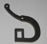
Just to give you an idea on how to do the torque...


You need to actually make an axle and put a contact surface between the flat surfaces of the axle and your part. Make the mesh pretty fine in those areas. If you use workbench (ansys) it allows you to put a torque load on a face. This is how I did it. The alternative is to put an equivalent opposing forces at a distance from the axis of rotation on both sides. There are a couple of ways to do it. I found the one with workbench was the easiest one.
 
Back
Top