Upload Your Circuit Schematics & Requests Here...

John that sounds great - I'm not in any crucial hurry for this - I'm still waiting for the motor and battery to arrive from China and I'm off to Italy for two weeks on 1st Aug - so I would guess I'm probably not going to get around to building the bike until I'm back... It'd be really great if I could have a "connect this red wire here on the controller to this yellow wire here on the brakes/motor/pedal controller/throttle" etc crib sheet worked out by then - I would guess that this would be a really useful thing to share here too as this seems to be a fairly popular setup for a DIY kit...
 
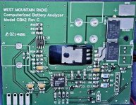
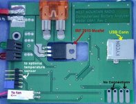
Figured I might as well see what was inside my Computerized Battery Analyzer and see if there was anything obvious that could account for the voltage being somewhat off on tests, especially the higher current ones. Well, other than dried out heatsink paste , I didn't see anything within my limited capabilities to play with.

But I thought some of you might like to see what they are like inside. (It wasn't quite what I expected)
CBA1.jpg
CBA2.jpg
 
RLT said:
Figured I might as well see what was inside my Computerized Battery Analyzer and see if there was anything obvious that could account for the voltage being somewhat off on tests, especially the higher current ones. Well, other than dried out heatsink paste , I didn't see anything within my limited capabilities to play with.

But I thought some of you might like to see what they are like inside. (It wasn't quite what I expected)
View attachment 1

I have it too and i tried to mod it to avoid the wor4st voltage reading dur to voltage loss in the wire...to see if i could add some current sensing wire to sens the voltage data directly thru auxilliary wire instead of the wire that circulate the discharge current
.. but it is nearly impossible due to the circuit desing...


there was many article on how to repair or prevent dammage of this analyzer on RCgroup forum..

This is a great unit but the voltage reading is poor!! and also it does not take account of the connections loss...!!

I've wrote to the designer of west mountain radio to see if he will make a newer version of it .. but it may take sometime..

Doc
 
Doctorbass said:
I have it too and i tried to mod it to avoid the worst voltage reading dur to voltage loss in the wire...to see if i could add some current sensing wire to sens the voltage data directly thru auxilliary wire instead of the wire that circulate the discharge current
.. but it is nearly impossible due to the circuit desing...

there was many article on how to repair or prevent dammage of this analyzer on RCgroup forum..

This is a great unit but the voltage reading is poor!! and also it does not take account of the connections loss...!!

I've wrote to the designer of west mountain radio to see if he will make a newer version of it .. but it may take sometime..

Doc

I'm thinking like you on this, Doc! I don't have a CBA like this, but after seeing the results that RLT posted in the headway thread I came to the conclusion that the device was measuring an extra 7 milli-ohms or so in his test setup. This error shows up the most when only one cell is being tested (low V output), and when high currents are being tested. This also makes us think that the cell has less capacity than it really has, because the voltage measured is used to calculate watt-hours (Wh = V * Ah).

Like you suggest, it would be great if we could have two seperate voltage sense wires that would be connected directly to the cell/batt under test, thus avoiding any added voltage drop produced by any resistance present in the CBA's output and in the external wires and connections to the cell/batt.

You say that
...it is nearly impossible due to the circuit desing...
to compensate for the extra resistance. Is this because of grounding issues in the voltage sense circuit going into the micro-controller? They don't use a differential amplifier I'm guessing?

OK, so to get around this to a certain extent it would be quite simple: Just ask the CBA company to add a software selectable compensation for this error! A user could then just select the equivalent resistance they have in their particular test setup - like about 7 mohms for RLT's tests here. The CBA's micro then just has to calculate the voltage drop produced by this added resistance (V drop = R ext * I test), and add it back onto the measured value... et voilà! :)

While they're at it, the CBA company might want to use this voltage compensation for the voltage cutoff setting too, since this same problem makes the cutoff voltage get activated too early, making it look like an even larger loss of watt-hours in your cell/battery! :?
 
ZapPat said:
Doctorbass said:
I have it too and i tried to mod it to avoid the worst voltage reading dur to voltage loss in the wire...to see if i could add some current sensing wire to sens the voltage data directly thru auxilliary wire instead of the wire that circulate the discharge current
.. but it is nearly impossible due to the circuit desing...

there was many article on how to repair or prevent dammage of this analyzer on RCgroup forum..

This is a great unit but the voltage reading is poor!! and also it does not take account of the connections loss...!!

I've wrote to the designer of west mountain radio to see if he will make a newer version of it .. but it may take sometime..

Doc


I'm thinking like you on this, Doc! I don't have a CBA like this, but after seeing the results that RLT posted in the headway thread I came to the conclusion that the device was measuring an extra 7 milli-ohms or so in his test setup. This error shows up the most when only one cell is being tested (low V output), and when high currents are being tested. This also makes us think that the cell has less capacity than it really has, because the voltage measured is used to calculate watt-hours (Wh = V * Ah).

Like you suggest, it would be great if we could have two seperate voltage sense wires that would be connected directly to the cell/batt under test, thus avoiding any added voltage drop produced by any resistance present in the CBA's output and in the external wires and connections to the cell/batt.

You say that
...it is nearly impossible due to the circuit desing...
to compensate for the extra resistance. Is this because of grounding issues in the voltage sense circuit going into the micro-controller? They don't use a differential amplifier I'm guessing?

OK, so to get around this to a certain extent it would be quite simple: Just ask the CBA company to add a software selectable compensation for this error! A user could then just select the equivalent resistance they have in their particular test setup - like about 7 mohms for RLT's tests here. The CBA's micro then just has to calculate the voltage drop produced by this added resistance (V drop = R ext * I test), and add it back onto the measured value... et voilà! :)

While they're at it, the CBA company might want to use this voltage compensation for the voltage cutoff setting too, since this same problem makes the cutoff voltage get activated too early, making it look like an even larger loss of watt-hours in your cell/battery! :?

Totally agree with you about that.. but there is only one thing about the compensation... it might be not accurate when you change of cell type pr cell connections... because it is not only the wire that introduce a V loss.. it is also the contact resistance of the connector between the cell and the cba's wires... so from one cell to another this connections resistance is often different... the results to test many different cells could not be accurate.

I think the compensation error (like the temp compensation they included for the temp sensing) is not a good idea.. it would only lower the problem but not solve it...

And yess, it's about the grounding issues in the voltage sense circuit going into the micro-controller. They don't use a differential amplifier.
 
Doctorbass said:
Totally agree with you about that.. but there is only one thing about the compensation... it might be not accurate when you change of cell type pr cell connections... because it is not only the wire that introduce a V loss.. it is also the contact resistance of the connector between the cell and the cba's wires... so from one cell to another this connections resistance is often different... the results to test many different cells could not be accurate.
[...]
And yess, it's about the grounding issues in the voltage sense circuit going into the micro-controller. They don't use a differential amplifier.

And I do also agree with you about this not being an ideal solution to the problem (software compensation of additionnal wire+contact resistance), but it has a few things going for it:
- Rapid, and even retroactive solution: It would be a minor issue for the CBA company to just make an updated version of the software. This would help all present owners to at least partially reduce this error. It would also happen faster than a major circuit change.
- Cost: differential amps are kind of expensive (as far as I know at least). This type of software change would not take long to do (only the PC's software code would need to be modified). Just add a compensation level selector in the PC interface, the user simply using a multimeter to calibrate it.

But hey, I don't have one, so I don't I will be the one to propose this to the CBA company! I just see it could help a few people here who already own one.

I think the compensation error (like the temp compensation they included for the temp sensing) is not a good idea.. it would only lower the problem but not solve it...

I still think lowering the problem substancially for free would be a bonus to you and all other owners of this CBA!
 
Hi all, first post.

I am planning on using a HXT brushless(80/100 130r/volt@ 72 volt/120 amp(72 volt/ 200 Amp controller)) for a three wheeled motorcycle. Tadpole.

I intend to use A123 cells(DeWalt 36 V(33 actual) 2.2 Ah X 2 = one 72(66 actual) volt cell X 5 cells = 15 Ah 72 Volt battery for 1000 dollars(approx.)

In addition, I have a Honda powered generator(3500 watt), I need a way to integrate the generator to provide power while traveling longer distances(series hybrid) while being able to limit amperage from the generator(instead of control voltage) when it is heavily loaded(3500 watts from gen), but also limit voltage applied to the batteries when lightly loaded(<3500 from gen)and charging batteries.

Would I be better off with an engine driven alternator at 72 volts and control(through the field coil) the amps until watts are less than max and then control the volts to 72(or charge cutoff)???

Any ideas???

Grumpy 8)
 
I can't think of any off the shelf solutions for that. Both an alternator and a standard ICE generator would require some hacking to provide a constant current instead of a constant voltage.

Most generators have some kind of field winding that controls the output. If you change the control for the field winding, you should be able to take the output straight to a bridge rectifier to the batteries. It would require some degree of reverse engineering the generator's regulator to figure out how to do a current mode.

It may be easier to change the voltage output on the generator and not worry about the current. If the voltage is set so that the batteries see their normal charging voltage, the current will taper off as the batteries charge up. There should be someplace in the existing circuit to place a resistor to drop the output voltage. This could be adjustable.
 
That generator seems pretty big to lug. I put a reply out in the Infinite Battery thread with my crazy idea...
http://www.endless-sphere.com/forums/viewtopic.php?f=3&t=5797#p87070

Basically, its a 4-stroke Rhyobi weed wacker motor with a motor as a generator. I've since been looking at Ametek motors...
http://cgi.ebay.com/AMETEK-7-Perman...oryZ3240QQssPageNameZWDVWQQrdZ1QQcmdZViewItem

Any thoughts on the level of crazyness and what circuitry might be in order? Also, what voltage motor would be best for a 48V battery setup?
 
fechter and StevenR

Thanks for your replies.

This is a curcuit to control first the amps and then the volts of a 12 volt engine driven alternator.

http://www.homepower.com/files/webextras/mark8.pdf

If I knew a way to get 60 or 72 volts out of a 200 amp alternator(rewind? higher rpm?) I would be halfway there. I also need a way to limit alternator output according to the max the batteries can accept+motor load up to the engines limits.

As far as the engine, Honda has a 5 1/2 hp OHC motor. If optimized to run at it's most efficient rpm it will be more than enough to generate 3500 watts. As to the generator look here...

http://www.ecycle.com/APU.html

With modification or a buck-boost maybe.

Grumpy 8)
 
I like the looks of the ecycle stuff. The motor/generators look like they have the right technology and the buck/boost converter may be the ticket for regen - get the voltage high enough to charge the battery. I think the regen from my C'lyte 4840 is just heating the phase cables from the motor and losing drive power due to increased resistance in the hot wires.

My concern about the ecycle gernerator is the size/weight. I'm looking to get 1000 watts or so from minimum weight. Efficience is good but not paramount. The Rhyobi ICE is fairly inefficient (although better than alot of them in the 50cc class) and I don't know what the AMETEK PMDC motors would do as generators but if I can get 1000+ watts from 15 pounds or so I would be very happy. This would be a reasonable load for my trailer with a 48V 20AH LiFePO4 pack - right around 35 pounds. I could charge one pack and/or use the output in a serial hybrid mode to get virtually unlimited range (I only think I could manage 200 miles or so with my butt and hands being the limiting factor)...
 
I think you can get about 48v out of a standard car alternator easily. You can put a resistor divider on the input to the regulator and dial it in for just about any voltage you want.

Somebody did something like this a while back and posted it here. Try the search function. I can't remember where it was. Seems to me he located a source for an aftermarket regulator that fit a car alternator and boosted the voltage way up.

Rewinding the alternator will certainly work also. I have done this before. It is a PITA.

The Ametek motor will have about the same watt rating as a generator as it does for a motor. You'd want to match the voltage output to the batteries at the most efficient RPM of the engine.

Another possible option would be to find a switching power supply with the desired output voltage and current limit, then just feed the input with raw voltage from the generator. Most of these switching power supplies are designed to operate over a very wide input voltage range. Be sure to find one with a 100vac-240vac input rating. They can run off AC or DC input. They can frequently run at much below the minumum rated voltage input.
 
Has anyone devised an inexpensive means of monitoring/displaying voltages of all the cells in a battery pack (perhaps 16 or 20 cells)?

Richard
 
rf said:
Has anyone devised an inexpensive means of monitoring/displaying voltages of all the cells in a battery pack (perhaps 16 or 20 cells)?

Richard


Hobby city is your friend.

6S for $5
http://www.hobbycity.com/hobbycity/store/uh_viewItem.asp?idProduct=6589&Product_Name=Battery_Monitor_2-6S

So for $15 you could watch the entire pack.
I have seen those on the Doc's bench

I have some of these:
http://www.hobbycity.com/hobbycity/store/uh_viewItem.asp?idProduct=7216&Product_Name=Wireless_battery_tracker_(6s_&_up_to_300mtr)_870mhz

More of a cool toy than anything. Watch out because the LVC beep is set to 2.7V, not 3.0V as it should be.

Remember if you order from Hobby City, always "EMS Express" shipping and NEVER by boat. (unless you like waiting months =). Usually get my goods within 5 days. Prices go down as you place more orders.

-Patrick
 
Even better:

http://www.hobbycity.com/hobbycity/store/uh_viewItem.asp?idProduct=7390&Product_Name=MP_LCD_Battery_Detector_6S
 
Hi All,

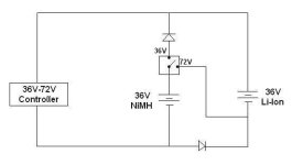
I have a bike with a Crystalyte 407 motor and two 36V 10Ah battery packs, one NiMH and one Li-Ion, currently wired in parallel. I'm looking to add a switch that will let me switch between 36V in parallel and 72V in series.

The very first post in this thread shows a wiring diagram for accomplishing this using a DPDT switch (2 inputs, 4 outputs), but I was going to try to do it with a SPDT switch (1 input, 2 outputs) and a few diodes. (I need the diodes in there anyways to prevent the different chemistry batteries from discharging into one another when they're in parallel.)

36V, 72V switch setup.JPG

Any thoughts on this approach? See any problems with my wiring diagram?

THANKS!
 
jsmay311 said:
Hi All,

I have a bike with a Crystalyte 407 motor and two 36V 10Ah battery packs, one NiMH and one Li-Ion, currently wired in parallel. I'm looking to add a switch that will let me switch between 36V in parallel and 72V in series.

The very first post in this thread shows a wiring diagram for accomplishing this using a DPDT switch (2 inputs, 4 outputs), but I was going to try to do it with a SPDT switch (1 input, 2 outputs) and a few diodes. (I need the diodes in there anyways to prevent the different chemistry batteries from discharging into one another when they're in parallel.)

Any thoughts on this approach? See any problems with my wiring diagram?

THANKS!

Looks like it will work OK. The diodes need to take the full operating current, so they will need a heat sink. If you look at the datasheet for a particular diode, you can estimate how much power it will dissipate. A small chunk of aluminum should be good.
 
Three requests, things that have been on my mind for a while:

1. Something to cut throttle on excess heat, not necessarily smoothly but the idea would be to somehow give seat of the pants feedback before cutting off, like perhaps going half throttle within 10 degrees of cutoff or something. Ideally the throttle would just have gradually less effect between two set temperatures. The one posted earlier in this thread would be OK to prevent motor destruction I guess, but it bothers me the way it cuts off sharply without warning once it reaches a threshold.

2. Something to work as a speed limiter on a brushless motor, again cutting off softly if possible.

3. Some way to recharge 2 AAA NiCad batteries off a 5v line like off that RC controller throttle adaptor thing's 5v line. The idea is that the batteries would recharge anytime an ebike battery is plugged in the ebike. The batteries would have wires going out to two LED blinkies so they could be operated just the same as if they had batteries. This way, the ebike's lights would run without an ebike battery, or with a dead battery. Also I would never have to recharge the light batteries manually, and it would (hopefully) save weight over having a set of batteries in each blinky light.


Fine by me if I have to use a drainbrain/multimeter/speedometer etc. or to fiddle around with various capacitor/resistor values, risk blowing stuff up, so long as it eventually gets somewhere close enough. In any case it's unlikely I'll be able to make use of any proposed circuits before summer or at least snowmelt.
 
Hello All!
I have posted the schematics for a dolphin 100 watt scooter motor controller in ZIP form. There are jpg's of the schematic as well as GIMP native pictures(multi layered) in case you need to make changes to the schematic. I also included most of the pertinent pdf files for the individual IC's.

Alan
 
Very nice! :mrgreen:
 
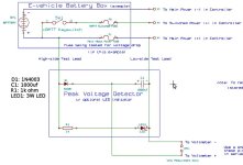
Simple, Cheap 'Peak Voltage Detector' (sample & hold) Tool

One of my first brain farts here was to wonder about losses through a 'fuse' . . . was I giving away any free horsepower? So I was asking another noob question in another post that lead to the idea of making a 'peak voltage detector' to use as a diagnostic tool.

This one is intended to be hooked up in an EV, to be in operation while actually driving under a load (unless you have access to a dyno . . . S.O.B.). I didn't want to be trying to focus on a DVM unravelling duct taped to my handlebars while navigating through Chinese traffic, so I set it for a slow response time. It gives me the luxury of making a run with my bike, then finding a nice safe, convenient spot to pull off the road, pull my DVM out of my bag and plug it in to the 'PVD', see what reading I've got. It also has an LED (pick your color, mines red) to give a quicky idiot light indicator that starts to show well at about 5v.

This thing (the tester) loses about .25v every 10 minutes so you've plenty of time to get yourself together.

I wanted to check the drop across my main power fuse, but you could use it on connectors too, and other things that were on the brain cell that I lost 20 years ago. BTW, the V-drop across a 30a 250v glass fuse was only 2.65v for my application (so no free lunch, er horsepower to speak of).

Mark

View attachment 1
PVD1a.jpg
IMG_0921a.JPG
View attachment 2
 
Is it complicated to make a electronic board that "read" normal throtle 0-5V and gives out 4 outputs, 2 digital and 2 analog. First analog gives 5-0V form input 0-2,4V, second analog gives 0-5V form input 2,6-5V and frist digital is on when input is below 2,45V and second digital is on when input is higher then 2,55V... second digital i s not necessery...
 
I purchased a 48v 20ah lifepo4 pack from vpower on eBay. After waiting about a month I received the battery pack and 2 amp charger. As soon as I connected the charger it blew I think it was because it was an SLA charger they sent me. I contacted vpower and they sent me another charger a 48v 5amp lifepo4 charger for $30.00 and received it about after 2 weeks and began using it. Today I got home and went to charge the battery pack and noticed the charger was totally off, I thought it was unplugged but it wasn’t. I opened the charger and noticed a burn and crack mark on what I think is a ceramic capacitor. This question goes out to anyone that can help me fix it, I have included some pictures so who ever responds can get familiar with which product I am writing about. I need to find the value or specs of the black ceramic capacitor, see below for pictures. Sorry about the quality if you need better pictures I should have a better camera later tonight.
This is the charger as seen on eBay http://i20.ebayimg.com/08/i/001/55/f7/501d_12.JPG

This is what it looks like http://www.infotroop.com/chargercover.jpg

This is what the charger looks like inside http://www.infotroop.com/chargerinsides.jpg

And this is the black ceramic capacitor I need to find the value of; it’s located on the wall plug side behind the fuse http://www.infotroop.com/xblow-resister-next-to-fuse.jpg and http://www.infotroop.com/blow-resister-next-to-fuse-.jpg
 
That could be an MOV (metal oxide varistor). Was the fuse blown? Where is it wired to?
 
Back
Top