Spec'd as a 72V 1200W 15FET controller (per the label which has 1000W crossed out and 1200W written over it).

First, a quick review of this controller, including a quick test on one of the bikes (later today if possible). Then onto the modifications/upgrades. This controller is from/for Migueralliart from this thread:
http://www.endless-sphere.com/forums/viewtopic.php?p=639963#p639963
and he has also sent the wire and power/phase connectors that will be used to replace the ring-terminals/cables presently on it. FETs are still on their way.


Apologies for some of the pics, I am still learning how to use the Rebel camera from GMUseless--it's much better than the Sony but is notably different in how it works in a few significant ways. If anyone needs better pics of something let me know and I will probably have figured out how to get htem by then.
Prior to modding it, I will test it to see if it even works, as it is new/untested, but prior to the test I thought I should open it up to verify it's assembly/etc., since it already was missing 1 screw off the wire-end cap and another was loose in the shipping bag. Plus I was curious.")

View attachment 17

Seems to ahve been a good idea, since I immediatley found two problems. The first is that they didn't bother to actually mount the FET heatsinkbar to the case, they just kinda crossthreaded the screws partly into the holes and left the bar catawhumpus at an angle with only the very bottom edge touching the case.


Next they left at least one SMT resistor (102 value) just floating around in teh case, or rather, stuck to the PCB's surface rather than in it's proper place and soldered down. I *hope* it is just an extra, because I don't see any specific place it should go, after a few minutes' examination. I did see two places it could go, but they appear to be deliberately unpopulated.

He already marked the wires he knew what they were for, but some are a mystery. I think some may be for the same purposes as thsoe on this 36V controller I tested out here:
http://www.endless-sphere.com/forums/viewtopic.php?f=4&t=21830
but not all of those were determined yet, either. I poked around a bit on ES and didnt' find this specific controller yet, but I didn't spend all that long at it. I will make a chart for which pads go to which wires and connectors later, for reference when modding it and to determine if any can simply be removed for simplification, and if any need to be added for his purposes.
PCB is marked "VP1000A_AVERGER_1.1". Outside label mentions "Sunny" for manufacturer.

FETs aren markked "RU7588R"
http://www.alldatasheet.com/datasheet-pdf/pdf/446158/RUICHIPS/RU7588R.html
75V 80A 7mohm, Vgs=10V Ids=40A Is (Diode continuous forward current)=80A. I might be misremembering, but most FETs use the Ids for their current rating, not the reverse-biased diode rating. Max Power dissipation at 100C is listed as 75W (150W for ambient but that's useless here).

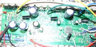
Main and phase Caps are 100v 220uF, and the available slots for them aren't all installed either. There are a pair fo wires listed as "volt meter" taht go directly to where a third main input cap should be, for isntance.
View attachment 12
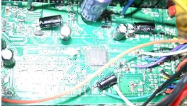
Some of the labelled PCB pads:
View attachment 8
They did sort of beef up the traces but the wire used doesn't actually go far enough, and I think i tis just sitting in the solidified solder, rather than being mounted to the traces. I've seen much worse on other controllers though.
I attempted to get the heatsink bar to mount flush with the case, but since the put the holes at the bottom of the bar instead of the middle, the holes are already crossthreaded at a severe angle, and the PCB/heatsinkbar is too wide to fit in the case with the bar correctly vertical, I can't get it to mount fully flush--only partly. I will have to drill new holes in it across the middle of the bar, and figure a way to tap them, or have the bolts come all the way thru between FETs and then use a clamping bar/nuts to secure it. I also will probably have to either sand the edge of the PCB or the back of the heatsink bar to get it to fit properly. I had to use visegrips at each end of the bar to clamp it to the case while I put the screws in just to get it as flat as it is.


Heatsink bar, failure of it to contact casing enough to do much of anything, fet clearances, other PCB shots, etc. Also heatsink bar screws are not all the same length, and some holes are stripped out from the crossthreading:
First, a quick review of this controller, including a quick test on one of the bikes (later today if possible). Then onto the modifications/upgrades. This controller is from/for Migueralliart from this thread:
http://www.endless-sphere.com/forums/viewtopic.php?p=639963#p639963
and he has also sent the wire and power/phase connectors that will be used to replace the ring-terminals/cables presently on it. FETs are still on their way.
Apologies for some of the pics, I am still learning how to use the Rebel camera from GMUseless--it's much better than the Sony but is notably different in how it works in a few significant ways.
Prior to modding it, I will test it to see if it even works, as it is new/untested, but prior to the test I thought I should open it up to verify it's assembly/etc., since it already was missing 1 screw off the wire-end cap and another was loose in the shipping bag. Plus I was curious.
View attachment 17
Seems to ahve been a good idea, since I immediatley found two problems. The first is that they didn't bother to actually mount the FET heatsinkbar to the case, they just kinda crossthreaded the screws partly into the holes and left the bar catawhumpus at an angle with only the very bottom edge touching the case.
Next they left at least one SMT resistor (102 value) just floating around in teh case, or rather, stuck to the PCB's surface rather than in it's proper place and soldered down. I *hope* it is just an extra, because I don't see any specific place it should go, after a few minutes' examination. I did see two places it could go, but they appear to be deliberately unpopulated.
He already marked the wires he knew what they were for, but some are a mystery. I think some may be for the same purposes as thsoe on this 36V controller I tested out here:
http://www.endless-sphere.com/forums/viewtopic.php?f=4&t=21830
but not all of those were determined yet, either. I poked around a bit on ES and didnt' find this specific controller yet, but I didn't spend all that long at it. I will make a chart for which pads go to which wires and connectors later, for reference when modding it and to determine if any can simply be removed for simplification, and if any need to be added for his purposes.
PCB is marked "VP1000A_AVERGER_1.1". Outside label mentions "Sunny" for manufacturer.
FETs aren markked "RU7588R"
http://www.alldatasheet.com/datasheet-pdf/pdf/446158/RUICHIPS/RU7588R.html
75V 80A 7mohm, Vgs=10V Ids=40A Is (Diode continuous forward current)=80A. I might be misremembering, but most FETs use the Ids for their current rating, not the reverse-biased diode rating.
Main and phase Caps are 100v 220uF, and the available slots for them aren't all installed either. There are a pair fo wires listed as "volt meter" taht go directly to where a third main input cap should be, for isntance.
View attachment 12
Some of the labelled PCB pads:
View attachment 8
They did sort of beef up the traces but the wire used doesn't actually go far enough, and I think i tis just sitting in the solidified solder, rather than being mounted to the traces. I've seen much worse on other controllers though.
I attempted to get the heatsink bar to mount flush with the case, but since the put the holes at the bottom of the bar instead of the middle, the holes are already crossthreaded at a severe angle, and the PCB/heatsinkbar is too wide to fit in the case with the bar correctly vertical, I can't get it to mount fully flush--only partly. I will have to drill new holes in it across the middle of the bar, and figure a way to tap them, or have the bolts come all the way thru between FETs and then use a clamping bar/nuts to secure it. I also will probably have to either sand the edge of the PCB or the back of the heatsink bar to get it to fit properly. I had to use visegrips at each end of the bar to clamp it to the case while I put the screws in just to get it as flat as it is.
Heatsink bar, failure of it to contact casing enough to do much of anything, fet clearances, other PCB shots, etc. Also heatsink bar screws are not all the same length, and some holes are stripped out from the crossthreading: