What happens when the battery current is restricted.

Waynemarlow

10 kW
Joined
Jul 9, 2016
Messages
778
Location
Bucks, England
On some of our EBike motors we are finding that we cannot limit the power low enough ( by design of the manufacturers ) to fully utilise the motor when say riding with other analogue bike riders or wanting to use more energy from ourselves.

If we can't lower the 1st level to say 200W's as the manufacturer has set the lowest level1 to say 300W's when the torque sensor is fully loaded and we have no means of changing the values of Level1 ( some manufacturers are now producing software to enable this at an individual owners level ), can we restrict the total power being fed into the motor from the battery ?

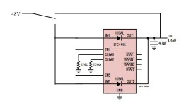
My question is if we say introduce something like LT.jpg as a raw example ( this is only the first example of current limting devices I found, I'm sure there is a load more and should not be used as an actual example ), which can restrict the total power getting to the motor, will if we say restrict the power to 150W's but keep the voltage the same, what will happpen ?

Moderator edit to add link to OP's other discussion on this topic
https://endless-sphere.com/forums/viewtopic.php?f=28&t=100777&p=1738154#p1737678
 
Anything that limits the current is going to be dissipating that power inside itself, if it's a linear device. If it's a switchmode device that is smoothing the voltage/current ripple enough to not blow up a controller (or a battery's BMS) then it's a full DC-DC converter, but either way it has to handle the full power of the whole system, all the time not just when it's doing limiting. This generally means it's going to be as large as the controller...and do the same job as the controller...so instead just use the controller to do this job--it's already designed to do it.


If the controller you're using does not have a user-adjustable current limit, you can change the circuit between the controller's internal battery-current monitoring shunt and the controller's MCU, to vary the voltage the MCU gets out of the circuit under your control.

If you change it so it gets less voltage than it should then it thinks the current is lower than it really is, and if more voltage then higher than reality.

Each controller is different, so there's no single universal drop-in board you would use on the same specific points on every board, but if you find the shunt, and trace teh thin traces from it back towards the MCU, there will be "stuff" between them. The scaling can be done in different places, but the simplest is at the output of the buffer (usually an op-amp, probalby an 8 or 12 or 16 pin SMD chip) from the shunt. We can work out details if you want to go this route.


Otherwise you can just get a DC-DC buck/boost converter with adjustable current limiting (and either a fixed voltage output or one that adjusts to what you want the controller to run on), that is capable of handling the full power (wattage) of the system under worst case conditions at highest assist level, and put that between battery and controller. (but it will be as big as or bigger than the controller, if it's really capable of that).


The device itself that you show above looks like part of a circuit, rather than a complete system to do the job in this case. I looked up the LTC4415 p/n that's on the drawing, and found this
https://www.analog.com/media/en/technical-documentation/data-sheets/4415fa.pdf
which shows it only handles up to 4A, at up to 5.5v, so it wouldn't work for your system.
Dual 50mΩ Monolithic Ideal Diodes
n 1.7V to 5.5V Operating Range
n Up to 4A Adjustable Current Limit for Each Diode
n Low Reverse Leakage Current (1µA Max)
n 15mV Forward Drop in Regulation
n Smooth Switchover in Diode ORing
n Load Current Monitor
n Precision Enable Thresholds to Set Switchover
n Soft-Start to Limit Inrush Current on Start-Up
n Status Pins to Indicate Forward Diode Conduction
n Current and Thermal Limit with Warning
n Thermally Enhanced 16-Lead MSOP and DFN
(3mm × 5mm) Packages

So...something similar to this with enough power dissipation capability and high enough voltage would work to limit current...but it will be large and/or have a large heatsink and/or have a noisy fan to move a lot of air (or all three), and it will be wasting the power of whatever differences there are across itself.

Note that generally devices that lower current do so by reducing the voltage available. That probably won't work for your purpose because the controller needs a certain voltage to operate; if limiting the current enough drops the voltage enough the controller will shut down.

I'm not certain how you can boost the voltage in the process of limiting current in a way that won't still drop voltage because the controller will be trying to draw more current than is now available to it....
 
Thanks Amberwolf for the reply.

If I generalise more by ignoring the circuit. What happens to a motor if you limit the total amps between the battery and motor but keep the voltage ?
 
Well, nothing different "happens" as such to the motor itself...but the controller will get less voltage from the battery (because of whichever converter you use to limit the current), so it then has less voltage to feed the motor. Assuming the current limit in the controller itself remains the same (meaning, the controller is limiting power to the motor by limiting the current only, not by limiting power), it will then have less wattage at the motor (because less voltage x the same current = less wattage). It's more complex than that, because other things are going on, but that's the basics.

In a simplified way of thinking about it: Unless the load itself changes resistance, you can only really limit amps by limiting the voltage at that point in the circuit.

A controller does it by slicing up (PWM) the voltage it outputs to the motor to lower the average voltage across the motor's resistance (PWM is used because this method wastes less power than doing it the "linear" way that circuit does (which wastes the unused power across it as heat inside it)).

(this is one reason why a switching power supply or SMPS is usually more efficient than one that uses a linear regulator; unless the SMPS is badly designed vs an excellent linear design, and/or the are poorly matched to their loads).


The only "simple" way to do what you're after is to modify the controller itself so it draws less current in the first place. Then the entire system works exactly like it normally does, except for drawing less current. It doesn't "know" it's drawing less current, because the modification "lies" to the controller about how much current is really passing thru it's shunt.
 
Back
Top