Reflector
10 W
What would cause a thumb throttle to exhibit 4V over its' full range?
I have two which I've tried and they both present a similar result (one with 4.32V one with 4.54V).
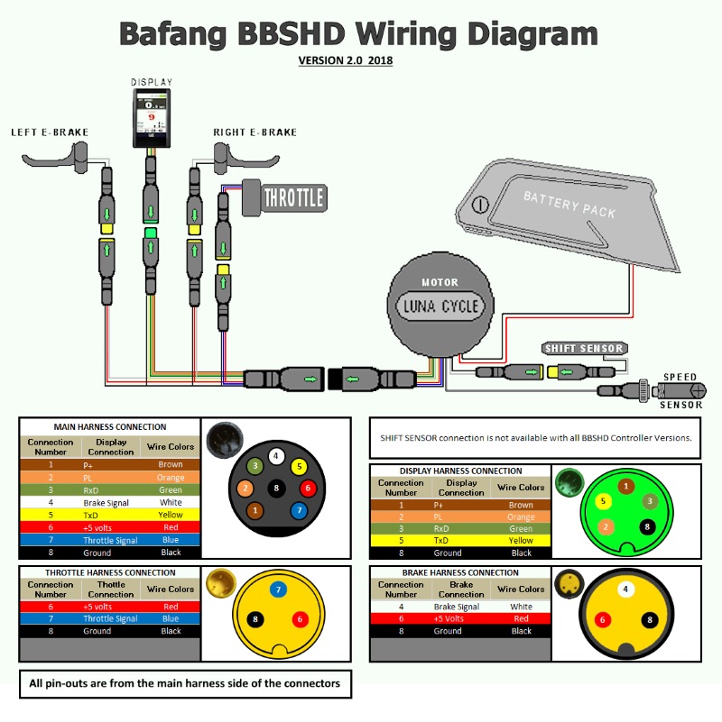
I've made a 'break out' cable so that I can test each throttle in situ with the Bafang powered up. Using this cable I've recorded
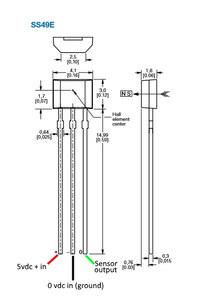
4.83V (Red) and 4.93V (White) which looks to me like the Hall signal is higher than the power supply.
My situation is (from a previously unresolved post) that of a WOT response to any use of the throttle.
A bench 'off bike' test using a 5V supply and resistor legs as probes into the Higo connector verify my initial findings.
Should I replace the sensor FET in each throttle to see if I can achieve the required less than 1V reading which I should be getting when the throttle is not activated? I've pored over Tommy Cat's excellent throttle dissertation as well as a few others but have not found anything describing the fun voltage exhibited throughout the whole range such as in this case.
The ground is intact between the rear wheel sensor (breakout cable) and other parts of the Bafang motor wiring loom e.g. the ground of the e-brake connection. If it's not a throttle issue, then it looks like I'll have to consider the $200AUD Bafang controller route.
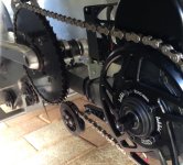
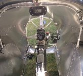
The PAS still works perfectly but my physical disability necessitates throttle use to gain sufficient momentum in my velomobile to get away from the cars.
I have two which I've tried and they both present a similar result (one with 4.32V one with 4.54V).
I've made a 'break out' cable so that I can test each throttle in situ with the Bafang powered up. Using this cable I've recorded
4.83V (Red) and 4.93V (White) which looks to me like the Hall signal is higher than the power supply.
My situation is (from a previously unresolved post) that of a WOT response to any use of the throttle.
A bench 'off bike' test using a 5V supply and resistor legs as probes into the Higo connector verify my initial findings.
Should I replace the sensor FET in each throttle to see if I can achieve the required less than 1V reading which I should be getting when the throttle is not activated? I've pored over Tommy Cat's excellent throttle dissertation as well as a few others but have not found anything describing the fun voltage exhibited throughout the whole range such as in this case.
The ground is intact between the rear wheel sensor (breakout cable) and other parts of the Bafang motor wiring loom e.g. the ground of the e-brake connection. If it's not a throttle issue, then it looks like I'll have to consider the $200AUD Bafang controller route.
The PAS still works perfectly but my physical disability necessitates throttle use to gain sufficient momentum in my velomobile to get away from the cars.
")