$14.99 72v Sunwin Controller

@markz - what is your ultimate goal? the original 15fets are good for between 52-60A without concern. I've run mine at 50a with no noticeable negative effects.

The 4110s have the lowest on-resistance = lower heat. The 4115s can handle higher voltage but at lower current and higher on-resistance. The 4310's can handle a bit more current than the 4110s but also with a bit higher on-resistance
 
Thanks, I've just read that in the 4110 vs 4115 thread. 60A is good, but I am power hungry. I would like to run 72V (with 80V caps) and 50A maybe 60A.

---------------------------------------------------------------------------------------------------------

I got some 10awg and 12awg Teflon PTFE wire left over, was thinking about using it to swap out the stock 12awg phase wires. Maybe double up my Teflon PTFE 10awg(5.26mm^2) to make it equal 7awg(10.5mm^2). Do it on both controllers, only issue will be what connector would fit.

I opened up my Lyen 18fet to see where the CA wires go, so I can figure out where on the SunWin the wires would go.

On the Lyen...
Blue and Black.jpg
Green and Yellow.jpg
Green and Yellow 1.jpg
Red.jpg
Lyen Backside Yellow Green Cycle Analyst.jpg
Lyen Shunt Topside.jpg
Lyen Shunt Backside.jpg

https://endless-sphere.com/forums/viewtopic.php?f=4&t=37964&p=939892&hilit=green+yellow#p939904

On the SunWin...
SunWin - Blue and Black.jpg
SunWin - Red.jpg
 

Attachments

  • SunWin USB-TTL.jpg
    SunWin USB-TTL.jpg
    372.2 KB · Views: 3,205
  • SunWin Hall area.jpg
    SunWin Hall area.jpg
    234.7 KB · Views: 3,205
  • SunWin1.jpg
    SunWin1.jpg
    292.2 KB · Views: 3,203
Those who have a Sunwin controller running, please could you post photos & explain the different cable connections?
 
Hey Suggs, my wires all have a little sticker on them.

Once I get my other half of the battery tab welded up I should have 56V and 8 - 9 Ah, not sure what the LVC is for the 60V 800W. I need to put back together the SunWin with wires connected to the USB-TTL pcb pads, comparing the SunWin to the Lyen I still can't quite figure out where the Cycle Analyst wires would go on the SunWin pcb.

Some notes as I have opened mine up and put it back together.
FET to Alum. shell screws have gobs of silicone or hot melt glue.
No paper on the underside of pcb to protect it from shortening out on Alum case.
End cap (non wire side) has a cheesy plastic film. I didnt see any on the wire side.
And it has the white substance on the backside of the FET heatsink.
 
Taken five weeks so far for mine. It's cheap but without field orientation I don't think non FOC controllers will stay pricey for long.

Are the traces beefed?
 
markz said:
Hey Suggs, my wires all have a little sticker on them, I posted a picture in a previous post in this thread.

Mine have labels on too but a couple of them are wrong and I also don't know what some of them do!
 
Samd said:
Taken five weeks so far for mine. It's cheap but without field orientation I don't think non FOC controllers will stay pricey for long.

Are the traces beefed?

Is field orientation the same as sinewave? Apologies but my knowledge isn't great yet.

Traces are reasonably beefed.
 
Is field orientation the same as sinewave? Apologies but my knowledge isn't great yet.
I have no clue what FOC is either, perhaps something to do with torque sensing or votlage/current sensing, sensing of some sort. Maximizing the field for optimal torque or efficiency. Alex Trebek am I right?
 
OMG !!! I just got this for a replacement for wifeee.... how the hell do you hook it up to make it work? I have nothing to go on as to what to connect to make it power up... yes I have power hall wires and phase wires connected but all the anti thefe AND POWER SWITCH? THIS IS FRUSTRATIONG any advice would be great.
 
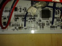
@markz - the hot glue on the heatsink mount screws is to prevent vibration backout - its a good thing
. The white substance is thermal paste aka heatsink compound and is used to make a surface more heat conductive - also a good thing. The PCB slides into grooves in the aluminum case so there's no way it can bottom out on the case and therefore the paper is not required. It should have the rubber sealer gasket on both end caps (in either clear or black silicone).

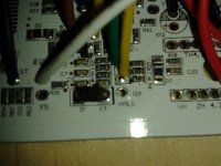
@lowberry - you only need to hook up the following wires to get the controller to work: 3 phase wires, 3 hall wires, power/ground and the lock wire. The lock wire must be connected to battery positive. All the other wires are optional. Of course you will need to figure out the correct combo of phase and hall wires or use the self-learn function.

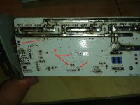
Regarding FOC, it's not clear in the documentation I can find whether or not FOC is implemented in the GPM8F3116A on these boards. I doubt it is, but can not confirm.
 
People are way off in their amperage ratings. I have ran 90 amps through my 15 FET controller daily with videos to prove it. They are the China 100v FETs I mentioned in my first post, and are rated for less power and with a higher on resistance than a 4110. I am powering a MXUS 4t with 20AH of LiPo at 72v. I had an 80 amp breaker that kept tripping, so I installed a 100 amp breaker. This is REAL WORLD and not math or written theory. My power meter shows 90 amps and 6400 watts drawn. While videoing, my 80 amp breaker tripped right when my power meter got to 80 amps, so my readings are very accurate. You cannot deny this or still claim that 60 amps is max for this controller. I have not modified this except for wires. I replaced the power wires with HK silicone 10 gauge because that is what the rest of the bike is wired with. The traces were already beefed.
 
@bsatom - I don't think anyone was claiming that 60A was a guaranteed maximum. the point was that the 45A label was a definite underrating and it was good for at least 50% more. sounds like you've even been able to push it further and verify it operates safely. good info. does it get hot in those conditions?
 
It only gets warm, not even hot. It is directly in front of my rear tire, so it is basically fan cooled. Also. It seems that only the 72v and higher versions are guaranteed to have the 100v 330w FETs I listed in the first post of this thread. Lower voltage versions seem to have the 75V FETs. I have no experience with those. I bought the 72v 500w version. Three of them actually. I still have two more brand new on the shelf, as I figured that I would blow one at the current I draw. These are EXTREMELY underrated, sleeper controllers.
 
Thanks for that great info, I might go ahead and buy a 72V flavor to get the 100V FET's.

I can't figure out one connection for the Cycle Analyst on these boards.
 
Which of these controllers can handle the highest voltage, and what is the potentiometer for?
 
Probably highest voltage?

http://www.ebay.com.au/itm/84V-1000W-Electric-Bicycle-Brushless-Speed-Motor-Controller-For-Scooter-E-bike-/391403307391?hash=item5b2174817f:g:GjsAAOSwrklVSaRo

I think the potentiometer just varies the Low Voltage Cutoff.

Also , I think the price varies with what mosfets etc they use (and then the buy it now difference)
 
Who just wants the PCB board from 1688 website?
They have a MOQ of 3, so for sure 3 of their Sine 18.
Where would one buy the aluminum case?

I was able to get bounded/binded, whatever that translated term means.
Im buying a few.

Its going to be a test order of their Sine 18, Im just buying straight off their website.

Price is, well price is listed on the 1688 website. Plus theres Taobao and Alipay.
 
Back
Top