
Very, very close, but not touching. A tiny, but consistent gap at rear sprocket is visual assurance there's no slop, movement, or misalignment at the drive sprocket/shaft (you'll see the 'tiny gap' change if something is amiss) - measure once... rotate the drive sprocket 90... measure again, once more @ 180. This is primarily for checking true parallel from motor shaft-to-axle.Why not quite touching?
You are using an out of date browser. It may not display this or other websites correctly.
You should upgrade or use an alternative browser.
You should upgrade or use an alternative browser.
1986 Daelim Trac "Hawk" moped conversion
- Thread starter harrisonpatm
- Start date
harrisonpatm
10 kW
- Joined
- Aug 8, 2022
- Messages
- 824
Excellent, good adviceVery, very close, but not touching. A tiny, but consistent gap at rear sprocket is visual assurance there's no slop, movement, or misalignment at the drive sprocket/shaft (you'll see the 'tiny gap' change if something is amiss) - measure once... rotate the drive sprocket 90... measure again, once more @ 180. This is primarily for checking true parallel from motor shaft-to-axle.
harrisonpatm
10 kW
- Joined
- Aug 8, 2022
- Messages
- 824
Great progress, for me at least. Got the front sprocket onto the motor shaft, by carefully measuring and drilling two divots into the shaft, that would receive the two set screw positions of the sprocket. Turned out just fine, very secure, it was a tight press fit anyway. I also got a key and I started to try to cut a key slot, but I it got real messy doing it by hand so I stopped before I got too far.


The motor shaft sticks out obnoxiously far, but I was going to print a guard for it anyway, so it shouldn't be a huge deal.
Then I got antsy and just went and mounted the whole chain drive. It was a bit off parallel on the first try, but after removing the motor and the wheel and adding necessary spacers, I got it lined up much better.


Dragged the whole thing over to my larger motorcycle's battery for a sketchy/premature bench test. Success! Wheel spins rather well and the chain doesn't fall off at full speed. For me it was rather loud, but I'm rather used to my silent hub motor so some chain noise is to be expected and I just need to get used to it.

Need to make sprocket guards for both the front and rear, I'll just print something simple


And that means the last big project is just the battery. Gonna be about a month before that is finished. All 312 cells are finished with their first charge, undergoing their 10day rest period for self-discharge test, then individually capacity testing. You can see the mounting plate I already made for it in the above pictures, and I have a pretty good idea of the final design, but I'm a CAD amateur, so go easy on my Blender drawings.

There's also some nasty rear wheel wobble from the new tire that still needs to be balanced. All little projects. Kinda cool that I got even this far on mostly scrap parts!
The motor shaft sticks out obnoxiously far, but I was going to print a guard for it anyway, so it shouldn't be a huge deal.
Then I got antsy and just went and mounted the whole chain drive. It was a bit off parallel on the first try, but after removing the motor and the wheel and adding necessary spacers, I got it lined up much better.
Dragged the whole thing over to my larger motorcycle's battery for a sketchy/premature bench test. Success! Wheel spins rather well and the chain doesn't fall off at full speed. For me it was rather loud, but I'm rather used to my silent hub motor so some chain noise is to be expected and I just need to get used to it.
Need to make sprocket guards for both the front and rear, I'll just print something simple
And that means the last big project is just the battery. Gonna be about a month before that is finished. All 312 cells are finished with their first charge, undergoing their 10day rest period for self-discharge test, then individually capacity testing. You can see the mounting plate I already made for it in the above pictures, and I have a pretty good idea of the final design, but I'm a CAD amateur, so go easy on my Blender drawings.
There's also some nasty rear wheel wobble from the new tire that still needs to be balanced. All little projects. Kinda cool that I got even this far on mostly scrap parts!
From-A-To-B
100 W
Love the sawmill look — it’s all coming along nicely!
harrisonpatm
10 kW
- Joined
- Aug 8, 2022
- Messages
- 824
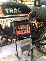
I got the rest of the wiring tidied up (there was a issue with the voltmeter on the speedo display, but that replacement is coming in the mail), and I put the tank, seat, and rear rack back on to get a look at the progress so far. Just needs the battery, really. There's an enormous wiring mess underneath the seat, which you luckily can't see once the seat is on!


Then I wanted to sit on the bike to be able to position the seat and handlebars. And dammit, the center stand/kickstand hits the chain when its up. Now that the rear sprocket is so much bigger.

Piece of scrap metal and rubber u-channel, made a stopper to prevent the kickstand from swinging all the way up.


Then I wanted to sit on the bike to be able to position the seat and handlebars. And dammit, the center stand/kickstand hits the chain when its up. Now that the rear sprocket is so much bigger.
Piece of scrap metal and rubber u-channel, made a stopper to prevent the kickstand from swinging all the way up.
harrisonpatm
10 kW
- Joined
- Aug 8, 2022
- Messages
- 824
Nearly done testing all the cells, but in the meantime I got my prototype for the battery case made up. Even though I plan to use it as is and put it on the bike, I'm still calling it a prototype because this is one of my most elaborate 3d-modeled projects I've ever done, therefore it's still rather messy in the finer details and I'm sure there will be issues installing the physical battery in it, and/or mounting it to the frame. It's a process for me, still learning, but I'm fairly pleased with how it turned out.


It's a fishtank! I wanted clear plexiglass sides so that I can see inside the battery. Both for maintenance so I can physically see the battery if there's an issue, but also aesthetics. I grew up in the 90s during the phase where all the electronic gadgets were made with clear cases so you could see the circuitry inside. Ah, to be back in those simpler times.... Also I was really liking the way @jonescg 's battery was turning out with his clear poly-carbonate case, and I wanted to copy that idea.
Test fit of all the components went fine, with plenty of wiggle room for the cables and balance wires, as well as padding around the corners to deal with vibration.

I didn't mount the plexiglass piece for the lid yet, because that's where the main + and - cables will exit and I haven't decided how to secure those yet.
The black is all 3d printed PETG, one piece each for the top and bottom, and 4 "legs", all printed seperately. 4 Threaded rods run all the way through the legs, sandwiching the top and bottom, so I'm not actually relying on any sort of 3d printed parts for the structure's pieces holding together. I fully expect something to break, not fit, or work poorly, and will probably be reprinting everything later, but that's what I like about 3d printing, it won't be difficult to do it again if I need to.
It's a fishtank! I wanted clear plexiglass sides so that I can see inside the battery. Both for maintenance so I can physically see the battery if there's an issue, but also aesthetics. I grew up in the 90s during the phase where all the electronic gadgets were made with clear cases so you could see the circuitry inside. Ah, to be back in those simpler times.... Also I was really liking the way @jonescg 's battery was turning out with his clear poly-carbonate case, and I wanted to copy that idea.
Test fit of all the components went fine, with plenty of wiggle room for the cables and balance wires, as well as padding around the corners to deal with vibration.
I didn't mount the plexiglass piece for the lid yet, because that's where the main + and - cables will exit and I haven't decided how to secure those yet.
The black is all 3d printed PETG, one piece each for the top and bottom, and 4 "legs", all printed seperately. 4 Threaded rods run all the way through the legs, sandwiching the top and bottom, so I'm not actually relying on any sort of 3d printed parts for the structure's pieces holding together. I fully expect something to break, not fit, or work poorly, and will probably be reprinting everything later, but that's what I like about 3d printing, it won't be difficult to do it again if I need to.
harrisonpatm
10 kW
- Joined
- Aug 8, 2022
- Messages
- 824
Cell testing done. I do a quick discharge/40p balance as the last step in the normal testing procedure, so that I know they're all at a storage voltage of 3.6-3.7v, but for this build I'll spend a couple of days doing a more thorough, more exact balance for the 200 cells I'll be using.
I've also changed my plans a bit. Originally I was going to use the 200 best cells out of the 312 tested. However, I am both surprised and excited to see that out of the 312 cells tested, every single one of them testing above 92% or original rated capacity.

Therefore, I want to consider using these same cells from BatteryClearingHouse for my more elaborate EX500 build this year. I will wait until I see these cells perform in the real world, voltage drop and all that, but my plan now is to use the 200 "worst" cells for the moped, and save the 112 best ones to roll into the stock that I'll want to use for the 840 cells I'm planning for the EX500. Because the "worst" cells are not actually even bad cells, perfectly usable, and that opens up the possibility of making an 8.5kwh pack for less than $750. So I'll want to reserve the best 112 leftover cells for that build later. Downside of course is that it will take quite a bit of time to individually test 840 more cells, but I'm in no hurry with that build.
I also have a hunch about my testers being less than accurate, and giving me a reading under what the cells can actually do. I have 1 Opus and 4 Liitokalas. The opus tester consistently gave me no cells under 3050mah, while all the liitokalas gave results of 2900-3150mah. I would have never noticed them varying their results before, because I normally tests dozens of different cells of hundreds of different possible ratings. But now having tested 312 cells that are all likely same or similar capacities, I theorize that the Liitokala tests discharge to 2.9-2.8v per cell, while the Opus may test to a lower voltage. These MH1 cells are specced to discharge down to 2.5v, so its possible that the Opus gives a more accurate/consistently higher mah rating than the Liitokala testers. This tracks with online reviews of the testers; Opus is generally considered to be more accurate, but while the main reason I have more Liitokalas is because I find their interface to be easier to use, it can't be ignored that the Liitokalas are the cheaper product. I plan to randomly retest a few of the lower-rated cells on the Opus to see if it gets a higher rating, to see if my theory is correct
Anyway, very pleased with my hunch of attempting low-voltage recovery of all these cells, it has clearly paid off in spades.
I've also changed my plans a bit. Originally I was going to use the 200 best cells out of the 312 tested. However, I am both surprised and excited to see that out of the 312 cells tested, every single one of them testing above 92% or original rated capacity.
Therefore, I want to consider using these same cells from BatteryClearingHouse for my more elaborate EX500 build this year. I will wait until I see these cells perform in the real world, voltage drop and all that, but my plan now is to use the 200 "worst" cells for the moped, and save the 112 best ones to roll into the stock that I'll want to use for the 840 cells I'm planning for the EX500. Because the "worst" cells are not actually even bad cells, perfectly usable, and that opens up the possibility of making an 8.5kwh pack for less than $750. So I'll want to reserve the best 112 leftover cells for that build later. Downside of course is that it will take quite a bit of time to individually test 840 more cells, but I'm in no hurry with that build.
I also have a hunch about my testers being less than accurate, and giving me a reading under what the cells can actually do. I have 1 Opus and 4 Liitokalas. The opus tester consistently gave me no cells under 3050mah, while all the liitokalas gave results of 2900-3150mah. I would have never noticed them varying their results before, because I normally tests dozens of different cells of hundreds of different possible ratings. But now having tested 312 cells that are all likely same or similar capacities, I theorize that the Liitokala tests discharge to 2.9-2.8v per cell, while the Opus may test to a lower voltage. These MH1 cells are specced to discharge down to 2.5v, so its possible that the Opus gives a more accurate/consistently higher mah rating than the Liitokala testers. This tracks with online reviews of the testers; Opus is generally considered to be more accurate, but while the main reason I have more Liitokalas is because I find their interface to be easier to use, it can't be ignored that the Liitokalas are the cheaper product. I plan to randomly retest a few of the lower-rated cells on the Opus to see if it gets a higher rating, to see if my theory is correct
Anyway, very pleased with my hunch of attempting low-voltage recovery of all these cells, it has clearly paid off in spades.
minsk
1 mW
suuuuuuper fun build.
harrisonpatm
10 kW
- Joined
- Aug 8, 2022
- Messages
- 824
Finally got around to assembling the battery pack, spot welded with my trusty microwave transformer spot welder. I was putting it off for awhile because we got hit with that cold snap in the midwest and I needed to spend some time making sure my house was staying warm in the power outages. No issues to report so far, turned out pretty much how I expected. The new method i tried was inspired by @jonescg , I'm not sure exactly what he did for his final build, but in this post, he describes a variation on the copper/nickel sandwich method, in which he used copper tape, rather than copper sheets. He was able to easily push 50ish amps from that connection, and I only need 10 amps max per series connection. I wanted to try it because copper tape is cheaper, easier to get, easier to pre-align on the nickel strip, and because it's so thin, even a crappy spot welder like mine could handle it now problem (I tested settings previously with some dead 18650s to make sure it was doable with my equipment).


The fold over always makes me nervous though...

Aside from the Kapton, I was able to print spacers for in between the two layers, that also do the job of "tucking" around the sides, to prevent future shorts. Tomorrow's game is tidying the balance wires and seeing how I'm going to manage to secure it into its box.


The fold over always makes me nervous though...
Aside from the Kapton, I was able to print spacers for in between the two layers, that also do the job of "tucking" around the sides, to prevent future shorts. Tomorrow's game is tidying the balance wires and seeing how I'm going to manage to secure it into its box.
Last edited:
harrisonpatm
10 kW
- Joined
- Aug 8, 2022
- Messages
- 824
Alright, battery is done! Was a bit of a squeeze to get it into the box, with padding, but that's good because it means there isn't any free space to vibrate around or jump when i hit a pothole.


I did have to cut away a section of the lid for the cable exit, something I hadn't planned, but it wasn't messy and I can always reprint the lid.
The way the padding ended up, I was able to mostly put it in the corners, not blocking the plexi, so I was still able to retain all 6 clear panels. Wouldn't want to mess with the aquarium aesthetic!


And it fits without issue into the cradle I made for it. You can see that I'll be employing a couple of nylon straps to secure it down to the frame. So I've successfully made a removable battery. Easily removable? No, I wouldn't say that, but it's not too hard!
And the bike is basically done, ready for test rides and to find and fix all the little issues that'll come up. We're still in the middle of our winter cold snap, so it'll be awhile, but I'm fairly pleased with how it turned out.


Anything stupidly obvious that I'm missing and needs to be fixed immediately before a test ride? I feel like this came together too quickly...
I did have to cut away a section of the lid for the cable exit, something I hadn't planned, but it wasn't messy and I can always reprint the lid.
The way the padding ended up, I was able to mostly put it in the corners, not blocking the plexi, so I was still able to retain all 6 clear panels. Wouldn't want to mess with the aquarium aesthetic!
And it fits without issue into the cradle I made for it. You can see that I'll be employing a couple of nylon straps to secure it down to the frame. So I've successfully made a removable battery. Easily removable? No, I wouldn't say that, but it's not too hard!
And the bike is basically done, ready for test rides and to find and fix all the little issues that'll come up. We're still in the middle of our winter cold snap, so it'll be awhile, but I'm fairly pleased with how it turned out.
Anything stupidly obvious that I'm missing and needs to be fixed immediately before a test ride? I feel like this came together too quickly...
Attachments
From-A-To-B
100 W
Nice work! I like your 3D-printed box and the aquarium aesthetic. I hope it lives a long life!
harrisonpatm
10 kW
- Joined
- Aug 8, 2022
- Messages
- 824
Thank you! I'm sure a year from now I'll be reprinting everything with new ideas that I'll have, I can never leave a project alone.Nice work! I like your 3D-printed box and the aquarium aesthetic. I hope it lives a long life!
Yes. You forgot to install the signage behind the clear plates:Anything stupidly obvious that I'm missing and needs to be fixed immediately before a test ride? I feel like this came together too quickly...

harrisonpatm
10 kW
- Joined
- Aug 8, 2022
- Messages
- 824
But I touched it, like, 12 times when i was putting it in!Yes. You forgot to install the signage behind the clear plates:
View attachment 346276
DaLanMan
10 kW
The wings are cute, but doesn't the harp music wear thin?
harrisonpatm
10 kW
- Joined
- Aug 8, 2022
- Messages
- 824
And it runs! Finally had a break in my weather (freezing, fog, rain, fog, fog, rain, ect.) to actually get on the moped and see if it works.
Starting with the first full charge. Using the JKBMS balance function to monitor a full charge to 83.6v, and holding it there to get a top balance. Then as I mentioned in a previous post, balance turns off and stays off, so that any imbalance that occurs later won't be hidden by the BMS.

Aaand she's off!


I gotta say, this definitely cemented my preference for hub motors. After a few miles to stretch out the brand new chain, I re-tensioned and significantly reduced the chain noise. But it's still there, and I'm accustomed to my near-silent hub motorcycle. She hits 35mph with no issue, maybe a bit faster (the speedo only goes to 30mph), and that's very close to a full twist of the throttle, so it seems like I did the transmission math correctly. Torque feels great, very similar levels of takeoff torque up to 20mph to my motorcycle. Starting from a stop is very sensitive/jerky, and that I'll chalk up to a combination of the 7:1 ratio, as well as the really really dirt cheap Aliexpress controller I'm using. No problem, I wasn't expecting awesome performance out of it, I can replace it later with a Fardriver or something. And it wasn't as noticeable if I give it a bit of a push start for a second, to get the motor shaft spinning before I give it throttle.
I'm using 20amps (1600w) to maintain 25-30mph on flat surface. I don't have an accurate way to measure short-term current draw on acceleration (I'm basically looking at my phone screen while accelerating from a stop, super safe), but it looked like I was pulling 40-50 amps max draw (about 3200-4000w) for a second or two, when I was really giving it throttle from a stop. Well within the 100amp max draw capability of my battery, really I'm only limited by the 3000w-rated controller right now. On paper, the battery should give me 20-25 mile range, I can update in a few weeks once I know what the real-world range turns out to be.
Very pleased with the motor. I have a temp readout for the motor on my dash, and it never got above 10 degrees C (ambient temp was 1-3 degrees C). Really good scrapyard find. Looking forward to the summer to see how warm it'll get on longer rides, want to see how much I can push it.
It's supposed to rain in my area for the next 3-5 days straight, so I probably won't be able to go out again for awhile, but I'll be ready as soon as the weather breaks again!
Starting with the first full charge. Using the JKBMS balance function to monitor a full charge to 83.6v, and holding it there to get a top balance. Then as I mentioned in a previous post, balance turns off and stays off, so that any imbalance that occurs later won't be hidden by the BMS.
Aaand she's off!
I gotta say, this definitely cemented my preference for hub motors. After a few miles to stretch out the brand new chain, I re-tensioned and significantly reduced the chain noise. But it's still there, and I'm accustomed to my near-silent hub motorcycle. She hits 35mph with no issue, maybe a bit faster (the speedo only goes to 30mph), and that's very close to a full twist of the throttle, so it seems like I did the transmission math correctly. Torque feels great, very similar levels of takeoff torque up to 20mph to my motorcycle. Starting from a stop is very sensitive/jerky, and that I'll chalk up to a combination of the 7:1 ratio, as well as the really really dirt cheap Aliexpress controller I'm using. No problem, I wasn't expecting awesome performance out of it, I can replace it later with a Fardriver or something. And it wasn't as noticeable if I give it a bit of a push start for a second, to get the motor shaft spinning before I give it throttle.
I'm using 20amps (1600w) to maintain 25-30mph on flat surface. I don't have an accurate way to measure short-term current draw on acceleration (I'm basically looking at my phone screen while accelerating from a stop, super safe), but it looked like I was pulling 40-50 amps max draw (about 3200-4000w) for a second or two, when I was really giving it throttle from a stop. Well within the 100amp max draw capability of my battery, really I'm only limited by the 3000w-rated controller right now. On paper, the battery should give me 20-25 mile range, I can update in a few weeks once I know what the real-world range turns out to be.
Very pleased with the motor. I have a temp readout for the motor on my dash, and it never got above 10 degrees C (ambient temp was 1-3 degrees C). Really good scrapyard find. Looking forward to the summer to see how warm it'll get on longer rides, want to see how much I can push it.
It's supposed to rain in my area for the next 3-5 days straight, so I probably won't be able to go out again for awhile, but I'll be ready as soon as the weather breaks again!
Aquarium needs some blue neon lighting.Anything stupidly obvious that I'm missing and needs to be fixed immediately before a test ride?

harrisonpatm
10 kW
- Joined
- Aug 8, 2022
- Messages
- 824
After a few rides, I can safely say that my range is around 35 miles per full charge, maybe 40-45. I took the cells down to 3.4v each, at which point they sag under acceleration to about 3.0-3.1v each. Even though the cells are rated to go down to 2.5v, I'm gonna keep my LVC higher than that for longer pack life. Especially since my range goal was 20 miles. Could have gotten away with a smaller battery! This gives me about 55-60wh/mile, or half what my full size motorcycle gets (edit: i mean that the wh/mile is more efficient with this lighter bike by 50% as compared to my full-side motorcycle; I realized it read badly).
An unfortunate downside to the huge rear sprocket is that I can't accerate too much while cornering . When the bike leans, the two rear shocks compress unevenly, and the rear wheel also skews, just a teeny bit. But it's enough that if I give it throttle during a lean, I hear chain skip because the rear sprocket is leaning with the wheel. Obviously the solution would be a primary reduction. But I don't have that level of fabrication available, and anyway it's just supposed to be a scrap build. Dont want to sink too much time and effort into it.
An unfortunate downside to the huge rear sprocket is that I can't accerate too much while cornering . When the bike leans, the two rear shocks compress unevenly, and the rear wheel also skews, just a teeny bit. But it's enough that if I give it throttle during a lean, I hear chain skip because the rear sprocket is leaning with the wheel. Obviously the solution would be a primary reduction. But I don't have that level of fabrication available, and anyway it's just supposed to be a scrap build. Dont want to sink too much time and effort into it.
Last edited:
I'd just change the word "gets" to "takes".This gives me about 55-60wh/mile, or half what my full size motorcycle gets (edit: i mean that the wh/mile is more efficient with this lighter bike by 50% as compared to my full-side motorcycle; I realized it read badly).
Similar threads
- Replies
- 8
- Views
- 917
- Replies
- 0
- Views
- 120
- Replies
- 164
- Views
- 2,951
- Replies
- 19
- Views
- 843