2 controllers in paralell for one hub motor, is it possible?

amberwolf said:
It doesnt cause shoot thru within a *single* controller--it would be from one controller into the other. If the top leg of any phase of controller A was turned on, and the bottom leg of the same phase of controller B was turned on, (however unlikely it might be to happen) and they are in parallel at the same battery and the same motor's phase connections, you now have a direct short from battery positive to battery negative, with only the FETs and the wires from the FET outputs to each other in the way.


And that's the paragraph that finally penetrates.

I've been thinking that the only difference was the presence of the other controllers output at the output of this controller; and not considering how that output gets there. Ie. Trying to consider the two controllers in isolation other than the paralleled outputs, and not considering that they effectively become a single large circuit.

We've been here before :( So once again, thank you for sticking with me.
 
I learned motor controller basics via 4QD's tec site like 10 years ago (doens't seem that long); Richard was interested enough in me learning (for reasons I don't recall) that he gave me a temporary access to the subscription site to read the really detailed stuff about the 4QD controller evolution and design, and it taught me a lot (even if Ican't remember hardly a lick of it anymore).

Since then I've fixed a few brushed and brushless ocntorllers, and tried to design my own (fail; powerstages get complicated), so I *think* I have a grasp of how stuff flows in there...but when it gets down to fine details I don't know much. :/
 
fechter said:
The controller is using the motor windings as the inductor in a buck converter topology. If the PWM isn't synchronized, sometimes they would be in phase and sometimes they would be out of phase. If the controllers aren't using synchronous rectification, then they shouldn't blow up from this but you could possibly get some surging in the output.

If the controller are using synchronous rectification, then you could get shoot-through and destruction.

It would be possible to synchronize the PWM by running the signals from the gate drives of one controller over to the other one. Not super hard, but would take some work.

Agree on synchronous rectification. This is one case where you want to use simple controllers that depend on diodes for carrying the circulating motor currents - not high performance or sine wave types. It has been demonstrated successfully and good that someone found the references to those experiments.

The right way to do this is to use one "brain" and multiple parallel output stages. I think Lebowski suggested this some time ago (and perhaps others), and it solves the various synchronization issues.

I also agree that regen may be problematic (unless synchronized gate signals are used).

In summary, paralleling low cost (non synchronous) sensored brushless controllers with disabled regen would be the most likely to work, and has been demonstrated.
 
Alan B said:
fechter said:
...If the controller are using synchronous rectification, then you could get shoot-through and destruction....

Agree on synchronous rectification. This is one case where you want to use simple controllers that depend on diodes for carrying the circulating motor currents - not high performance or sine wave types.
... (non synchronous) sensored brushless controllers with disabled regen would be the most likely to work, and has been demonstrated.

Could I prevail upon you or fechter to expand on "non-synchronous rectification" and how you (I) can recognise it?
 
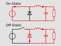
In a buck converter topology, when the switch is off and the magnetic field is collapsing, the current is circulated by a diode.

Buck Converter Basics.JPG

In a motor controller, this diode is really the body diode in the low side FET. When this diode is conducting, there will be a voltage drop across it that might be about 1v, which generates significant heat. In more advanced systems, the low side FET turns on when this happens to reduce the voltage drop and heating. The timing has to be precise, as the high side and low side can't be on at the same time or it will blow up (shoot through).

It's hard to tell what flavor you have just by looking. I tell by using an oscilloscope to look at the gate drive signals. With a motor running, the low side gates of a non-synchronous controller will be switching at the commutation frequency, in sync with the hall sensors. In a synchronous controller, the low side FETs will be switching at the PWM frequency during part of the cycle. This is typically over 10khz.
 
fechter said:
In a buck converter topology, when the switch is off and the magnetic field is collapsing, the current is circulated by a diode.

Buck Converter Basics.JPG

In a motor controller, this diode is really the body diode in the low side FET. When this diode is conducting, there will be a voltage drop across it that might be about 1v, which generates significant heat. In more advanced systems, the low side FET turns on when this happens to reduce the voltage drop and heating. The timing has to be precise, as the high side and low side can't be on at the same time or it will blow up (shoot through).

It's hard to tell what flavor you have just by looking. I tell by using an oscilloscope to look at the gate drive signals. With a motor running, the low side gates of a non-synchronous controller will be switching at the commutation frequency, in sync with the hall sensors. In a synchronous controller, the low side FETs will be switching at the PWM frequency during part of the cycle. This is typically over 10khz.

Thanks fechter; that helps.
 
Standard low budget ebike controllers rarely use synchronous rectification. The inherent body diodes in the FETs are "free" and do the job in a simpler way, software wise, though they do it at greater loss.

Controllers that do synchronous rectification have more complex software and a bit more circuitry to do things to recognize when entering the regen region that occurs when the PWM throttle is backed off, most riders do not like the very strong deceleration that occurs with synchronous rectification as the PWM is lowered. So the controller must recognize this is occurring and change the mode of the controller or match the PWM to the back EMF so it does not occur, or set a lower value of regen for this condition (called "slip regen") to make it feel like a gas engine decelerating.. The benefit of this feature is the controller runs cooler, but the energy savings is not large enough to affect the range significantly so there is not much benefit from the low cost system manufacturer's point of view. From our point of view it allows the controller to be smaller, or handle a little more current. Really tiny controllers and high tech offerings with more engineering investment would benefit most from it and be able to make it work, so you will likely find it there.

I expect all the FOC sinewave controllers are doing Synchronous Rectification, and a few of the Kelley models are doing it. I don't think any of the garden variety low cost hall sensored trapezoidal controllers are.
 
Back
Top