themadhatter106
100 W
So my ping is getting quite old. At 5 years now It sags down a lot in the winter time especially. I've had quite a few hiccups and failures with my ping, knowing all of the failures that have happened I know that I can build a better pack myself.
I ordered 32 cells from OSN Power this past summer and for a while I schemed and planned how I was going to connect them. At first I was thinking to skewer all of the tabs with a threaded rod and stack blocks of copper and plastic to build the pack. I even bought all of the parts for this method. Then at the last second I changed my mind and decided that it would be too difficult to change once cell in the pack and I was also worried about the possibility of the threaded rod shorting out cells if the shrink tubing/plastic cover ever wore through or broke.
I decided to use agniusm's PCB design as the base for the build however, I did things differently than he did in his kit. I give alot of credit to agniusm for making his PCB design open source. I had a lot of 12S boards spun so that I can just cut them down to size and make whatever size pack I want. In order to make the pack I had top punch holes in all of the cells, I used a $20 sheet metal punch I bought off of ebay. It worked great, I punched 4mm holes to have a little bit of leeway for the 3mm bolts that will be clamping all of the tabs.
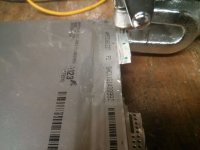
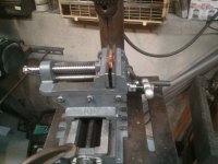
I then cut and drilled all of the copper blocks. I should mention that these blocks are taller than they need to be for the PCB method of attachment. Also, they dont need to be copper since they are not carrying any current, with the exception of the blocks for each of the ending cell where I solder wires onto. I should also mention that on my bike I have my battery in a split pack configuration and mount it low on my front rack. So the 20S pack is split into two 10S sections.
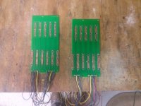
When I had all of the PCBs spun I forgot to make holes in the solder mask for where the tabs would be clamped down to so I took a dremel tool with a sanding wheel and sanded off the solder mask on those spots. I also soldered on all of the sense wires for the BMS. I decided to not use connectors at the PCB because that's the way my ping has been for years and it was never a problem.
In lieu of the tapped aluminum block which agniusm uses on the cell side of the board I used nylon lock nuts. The aluminum block would provide more consistent clamping pressure on the tabs but I think that with three screws per tab the clamping pressure should be more than enough for good conductivity.
View attachment 6
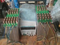
For a BMS I went with a Bestech Power 80A discharge 20A charge BMS. I had them set the balance voltage at 3.6 V. I figure that If I want more current I can bypass the BMS which is why I soldered in a BMS bypass wire so I can plug in negative power wire before the BMS. I used 75A Anderson connectors which I got for free from a box of junk at my school's electric vehicle garage.
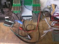
When I tried to charge all of the cells and get them all balanced all of the cells went right up to 3.6V except for one cell. The BMS wouldn't balance it so I tried manually charging it with the power supply and it just drew 200 mA for days and when I would disconnect the power supply the cell measured 3.3 V. Must be one of those OSN Power duds.
In order to discharge test the cells I did it one of the cheapest and most versatile ways possible. Bought some a bunch of nichrome wire and calculated the correct length of wire so that it will dissipate plenty of power for the pack voltage without melting the nichrome. Then I wrapped the nichrome wire around a cinder block. The cinder block setup pulls 45A. I designed it that way so I wouldn't overheat the 45A Andersons that I have on my watt-meter.
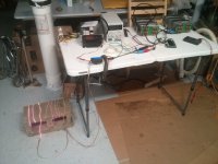
I noticed on the first discharge test that one cell was reaching 2V and cutting out the BMS at about 10 Ah. Another dud! So I replaced the cell with another one. In order to charge my battery I put a lab power supply in series with a 1,200W BMS battery charger. I tried to adjust the voltage of my battery charger to 72V using the potentiometer inside but unfortunately the highest it will go is about 62V . That's a shame, looks like I will need to buy a new charger if I want to have something portable.
So far I have cycled the pack 10 times (0.5C+,2C-). Each time the pack puts out an average of 20.4 Ah before a cell hits the 2.0 V cutoff voltage. Even at 45A with the laser cut (butchered) negative tabs the copper blocks barley get warm. It should be fine at 80A peak. Although I am planning for 100A peak with bypassing the BMS.
In order to compress the cells I had an idea of using acrylic and hose clamps. When I tried this I discovered that the acrylic was bowing out and the pressure was no were near even. To fix this I cut strips of 1/8" steel to put underneath the hose clamps in order to provide more even pressure across the acrylic. As far as it looks its much better than with no metal strips as there is no visible bowing of the acrylic. I didn't want to risk having too much pressure, especially if the pressure wasn't exactly uniform so I tightened the hose clamps just enough that I couldn't move them around with my hands.
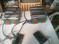
I ride in the winter time and one of the main reasons I am making this battery pack it because my ping will sag soooo much when it is cold that the cutout will engage even when the pack is at 50% dod and pulling <1.5C. Foam insulation helped with this so I am doing the same on my A123. I also insulate my battery pack so that when my battery is cold and I am riding home my pack will have warmed up above freezing so that I can charge it right when I get home. I use 3/4" Styrofoam insulation to surround the whole battery pack for insulation. I intend to use insulation crack filler on the top of the pack where there is a gap between the cells and the foam. You may also notice the BBQ thermometer I have there. I mounted the thermistor to the side of the cell foil with thermal epoxy. I only rigged this up on one of the packs just to give me an idea of how effective my insulation is and whether my battery is warm enough to charge.
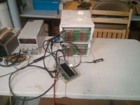
This weekend I also made my battery pack mount. I am a poor college student and I had some spare EMT hanging around so instead of buying steel flat bar I cut and flattened 3/4" EMT to make the frame for mounting the battery pack.
Next weekend I hope to get these packs mounted to my bike and start some real testing!
I ordered 32 cells from OSN Power this past summer and for a while I schemed and planned how I was going to connect them. At first I was thinking to skewer all of the tabs with a threaded rod and stack blocks of copper and plastic to build the pack. I even bought all of the parts for this method. Then at the last second I changed my mind and decided that it would be too difficult to change once cell in the pack and I was also worried about the possibility of the threaded rod shorting out cells if the shrink tubing/plastic cover ever wore through or broke.
I decided to use agniusm's PCB design as the base for the build however, I did things differently than he did in his kit. I give alot of credit to agniusm for making his PCB design open source. I had a lot of 12S boards spun so that I can just cut them down to size and make whatever size pack I want. In order to make the pack I had top punch holes in all of the cells, I used a $20 sheet metal punch I bought off of ebay. It worked great, I punched 4mm holes to have a little bit of leeway for the 3mm bolts that will be clamping all of the tabs.

I then cut and drilled all of the copper blocks. I should mention that these blocks are taller than they need to be for the PCB method of attachment. Also, they dont need to be copper since they are not carrying any current, with the exception of the blocks for each of the ending cell where I solder wires onto. I should also mention that on my bike I have my battery in a split pack configuration and mount it low on my front rack. So the 20S pack is split into two 10S sections.

When I had all of the PCBs spun I forgot to make holes in the solder mask for where the tabs would be clamped down to so I took a dremel tool with a sanding wheel and sanded off the solder mask on those spots. I also soldered on all of the sense wires for the BMS. I decided to not use connectors at the PCB because that's the way my ping has been for years and it was never a problem.

In lieu of the tapped aluminum block which agniusm uses on the cell side of the board I used nylon lock nuts. The aluminum block would provide more consistent clamping pressure on the tabs but I think that with three screws per tab the clamping pressure should be more than enough for good conductivity.
View attachment 6

For a BMS I went with a Bestech Power 80A discharge 20A charge BMS. I had them set the balance voltage at 3.6 V. I figure that If I want more current I can bypass the BMS which is why I soldered in a BMS bypass wire so I can plug in negative power wire before the BMS. I used 75A Anderson connectors which I got for free from a box of junk at my school's electric vehicle garage.

When I tried to charge all of the cells and get them all balanced all of the cells went right up to 3.6V except for one cell. The BMS wouldn't balance it so I tried manually charging it with the power supply and it just drew 200 mA for days and when I would disconnect the power supply the cell measured 3.3 V. Must be one of those OSN Power duds.
In order to discharge test the cells I did it one of the cheapest and most versatile ways possible. Bought some a bunch of nichrome wire and calculated the correct length of wire so that it will dissipate plenty of power for the pack voltage without melting the nichrome. Then I wrapped the nichrome wire around a cinder block. The cinder block setup pulls 45A. I designed it that way so I wouldn't overheat the 45A Andersons that I have on my watt-meter.

I noticed on the first discharge test that one cell was reaching 2V and cutting out the BMS at about 10 Ah. Another dud! So I replaced the cell with another one. In order to charge my battery I put a lab power supply in series with a 1,200W BMS battery charger. I tried to adjust the voltage of my battery charger to 72V using the potentiometer inside but unfortunately the highest it will go is about 62V
So far I have cycled the pack 10 times (0.5C+,2C-). Each time the pack puts out an average of 20.4 Ah before a cell hits the 2.0 V cutoff voltage. Even at 45A with the laser cut (butchered) negative tabs the copper blocks barley get warm. It should be fine at 80A peak. Although I am planning for 100A peak with bypassing the BMS.
In order to compress the cells I had an idea of using acrylic and hose clamps. When I tried this I discovered that the acrylic was bowing out and the pressure was no were near even. To fix this I cut strips of 1/8" steel to put underneath the hose clamps in order to provide more even pressure across the acrylic. As far as it looks its much better than with no metal strips as there is no visible bowing of the acrylic. I didn't want to risk having too much pressure, especially if the pressure wasn't exactly uniform so I tightened the hose clamps just enough that I couldn't move them around with my hands.

I ride in the winter time and one of the main reasons I am making this battery pack it because my ping will sag soooo much when it is cold that the cutout will engage even when the pack is at 50% dod and pulling <1.5C. Foam insulation helped with this so I am doing the same on my A123. I also insulate my battery pack so that when my battery is cold and I am riding home my pack will have warmed up above freezing so that I can charge it right when I get home. I use 3/4" Styrofoam insulation to surround the whole battery pack for insulation. I intend to use insulation crack filler on the top of the pack where there is a gap between the cells and the foam. You may also notice the BBQ thermometer I have there. I mounted the thermistor to the side of the cell foil with thermal epoxy. I only rigged this up on one of the packs just to give me an idea of how effective my insulation is and whether my battery is warm enough to charge.

This weekend I also made my battery pack mount. I am a poor college student and I had some spare EMT hanging around so instead of buying steel flat bar I cut and flattened 3/4" EMT to make the frame for mounting the battery pack.
Next weekend I hope to get these packs mounted to my bike and start some real testing!

