A Simpler E-Bike Display

Swordman

100 mW
Joined
Jan 9, 2007
Messages
40
I've been thinking of building a homemade DrainBrain. But, I really didn't see the point until now as the DrainBrain is a good product and the only thing, other than learning, would be to save a few bucks. So, I've thought about what I could add to a device of this type, and I think the answer is simplification.

Let me give you an example. They produced at one time a 280ZX with digital gauges. I sat in this car once, and it was atrocious. Imagine 7 segment amber displays everywhere in your vision. While it was a cool light show, it was very distracting and not all that intuitive.

I apply this same example to the current digital meters out there (the DrainBrain and the Watts Up). They give you a lot of information in a compact LCD display. While this is fine for the gearheads and designers out there, a simpler top level display is needed.

Here's the type of information I see I need:

- Show me how long I can use the motor before I have to turn around and go home (a fuel gauge).

- Show me how hard I'm using the motor (instantaneous amp usage).

- Tell me how long I've used the motor (elapsed motor usage time).

- Warn me when I've exceeded some set limits (low battery voltage cutoff, time to turn around and go home)

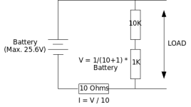
Attached is an example picture of what I'm talking about. What do you guys think?
 
If you check around the web, you'll find several people working on Palm based metering (Optibike among them) which would be my preference. I'm a big believer in separates, that is I detest having to cycle thru different modes to get the info I want unless its for some very infrequently used functions & prefer the basic stuf like volts & amps be permanently on display.

I could buy two Drainbrain's I suppose, but with something Palm based you'd be able to format the output however you like. Numerical, bar-graph, or both. Sound events, alarms, data logging, etc. & have various layout 'skins' for when you get bored & want a different look. With some programming it would be possible to display real time projected range as power consumption changes. Next to V/I, the next most critical metering I want is battery & motor temp.

Unfortunately my ambition exceeds my ability :cry: & unlike you need a crash course in microcontroller programming. Just need to get my feet wet & start with the basics.

http://optibike.com/images/pda/1.jpg
 
Yes I like the bar graph much more than digits only.

Multi-color would be really cool (red zones, etc.) I'm not sure if cheap color displays exist or if they could be properly driven from a small Atmel.

I have seen multi color LED bar graphs. It might be possible to have a separate bar graph and LCD digital display.
 
Toorbough:

While I like the flexibility that a PDA can provide, an IPAQ-based solution is not exactly an inexpensive way to go. I mean, the IPAQ itself is around $400 with the sensing apparatus probably another $50 - $100. I guess that is ok considering the Optibike is $5500, spending $500+ on a gauge is acceptable. But, the IPAQ-based solution costs more than my whole bike, motor and batteries included.

Fechter:

I'm in the planning stages now. I'm gonna try with the display format I've come up with, probably using the filled in square character instead of the asterisks. I've gotten A-D conversion working with the microcontroller, so most of my initial experimentation is done. I'm gonna probably purchase a few of those allegro hall sensors and see how they work for current measurement. They provide both +/- current sensing, output 2.5V for a current of 0, and have a sensitivity of 40mV / Amp.

As for a color display, I did think about the old magnavox odyssey, with its plastic overlays, but I'm not sure how well that would work on an LCD display.
 
No, no, no. I'm not suggesting going with an Ipaq. It was just a convenient illustration to convey the underlying idea. The particular platform is irrelevant.

I got an old Palm M105 that I paid 20 bucks for a few years ago & I'd use that if I knew how to program the damn thing. A Palm is much like any other MCU but its prime benefit is that all the display functions are already there for you. It even has a backlight. Like you said, flexability. If someone wants a colour display & bluetooth then there a whole range of possibility. Personally I prefer the mono screen cuz it sux less juice. Oh well, not your cup of tea I guess. :?
 
Toorbough,

I think using a PDA is a great idea, I just am trying the microcontroller approach at this time. I'm just not sure how you would interface analog inputs to the PDA (the microcontroller has digital and ADC lines built in) and I'm not sure I like something that big on a bike. Maybe just using the PDA for the display with a microcontroller for gathering the data and sending it to the PDA would work.
 
I seriously think you would end up with a microcontroller doing the sampling and then packing the information up and sending it out to the pda serially. Nothing against the pda processing the information for displaying it on a graphic screen like that takes more processor power than just sampling the data. Its a whole different world from the nice little alphanumaric lcd displays.
Joe
 
Yes, I'm still at this. I've come a long way in a few weeks, and am getting close to something that works.

Could someone describe how devices like the drain brain and watts up meters measure both current and voltage using a shunt?

I can understand how they measure current, just measure voltage across a known resistance value. But, I just don't see how there is enough information to get battery voltage knowing only the current and a known resistance.

I'm using a voltage divider (two resistors in series from + to -) right now to get the battery voltage down to a point where it is compatible with the ADC on the microcontroller. But, I'm not sure using a voltage divider is going to work because once you hook a load in parallel with your voltage divider, your overall circuit resistance changes.
 
Thanks Reid. It helped some, but I guess a diagram of my test circuit is needed.

I have no problem with determining the current. It is simply a matter of measuring the voltage across a shunt resistor and dividing by the shunt's resistance. It is currently 10 ohms for my test setup but will be much less than an ohm for a real shunt. Or I could use one of those allegro hall sensors if I ever buy some.

I'm having a problem with the voltage. I'm using a voltage divider to get the battery voltage down to a level I can measure with the microcontroller. In this case 2.56 volts. This works great until you hook a load, for my test case a 1K ohm resistor, in the real case, the motor controller, to the circuit.

Then, the voltage reading is incorrect since the resistance of the load is affecting the overall resistance of the circuit. I'm not sure how to account for that.

Anyone, anyone. Or please tell me the correct way to measure the voltage if I am doing it wrong.
 

Attachments

  • ebike_meter.png
    ebike_meter.png
    4.9 KB · Views: 5,676
Swordman said:
Then, the voltage reading is incorrect since the resistance of the load is affecting the overall resistance of the circuit. I'm not sure how to account for that.

Anyone, anyone. Or please tell me the correct way to measure the voltage if I am doing it wrong.

I think you have it right, basically measure the voltage across the shunt and use the resistance to figure out the current. But you can't use the shunt to measure voltage of the whole circuit, don't you need another set of wires to do that across the batteries?
 
Reid Welch said:
Isn't that shunt on the wrong side?

And shouldn't that be 9k if you're going for a nine-tenths reduction?
(you measure the voltage across the 1k, right?)

If I'm off base, apologies--am really fuzzy/rusty on this simple stuff.

I'm glad to see someone remembers their high school electronics.
Yes, you would need 9k if you wanted a 1/10 output. I usually cheat and use a trimmer pot to dial it in, since precision 9k resistors are hard to come by.

The voltage divider is configured correctly, but since there's a significant voltage drop in your shunt, that would affect the readings. Moving the shunt to the other side of the divider would be one way around that. In actual practice, the shunt would be like 1 milliohm and have a maximum voltage drop of 1mv per amp, so the effect on the measured voltage would be minimal.
 
Reid Welch said:
Isn't that shunt on the wrong side?

And shouldn't that be 9k if you're going for a nine-tenths reduction?
(you measure the voltage across the 1k, right?)

If I'm off base, apologies--am really fuzzy/rusty on this simple stuff.

Yes, the shunt is on the wrong side. And yes, I would need a 9K resistor for a 10:1 reduction. I currently am using what I have and will need a 40:1 reduction for a max voltage range of 100V which is what I'm after. And I'm equally fuzzy on the practical stuff also.
 
fechter said:
I'm glad to see someone remembers their high school electronics.

Well, it's actually sadder than that. I didn't take high school electronics but I do have a 4 year EE degree. I can caculate voltages and currents and know how the components work and all that, it's just the practical stuff I'm rusty on. Of course, the fact that it's been 20 years since that degree might have something to do with it. :)

Now, thanks everyone for pointing out the incorrect shunt position. But the problem I'm after is the voltage measurement. Someone please correct me if I'm wrong, but unless the load has a sufficiently high resistance, it will affect the voltage reading.

Am I missing something here?
 
Well,

After some spreadsheet engineering and actually using my brain, I believe my whole problem was incorrect placement of the shunt. If I put that in the right place, then the voltage divider should work fine. I kept thinking that the load would affect the voltage divider. But the voltage divider is across the battery, so all the load affects is the total current of the circuit.

Can someone give me an amen here?
 
Swordman said:
Well, it's actually sadder than that. I didn't take high school electronics but I do have a 4 year EE degree. I can caculate voltages and currents and know how the components work and all that, it's just the practical stuff I'm rusty on. Of course, the fact that it's been 20 years since that degree might have something to do with it. :)
I'm just a guilty, 10 years ago I was in college for electronics and heck I keep getting everything wrong. I remember when they still taught us that current flows from positive to negative, but now it's found to be false, current flows from negative to positive. Then, it seems that the AC has less resistance loss than DC urban legend was also wrong. I kind of wonder where my teachers were getting this stuff after everyone keeps correcting me, LOL.

I still remember enough to be dangerous, but after so long of not using any of it (since computer programming and hardware has been my career). I'm glad someone here keeps up their skills to help the rest of us :wink:
 
Well,

I just went home for lunch and tried the correct shunt placement. Works like a charm. I just couldn't figure out why when I placed a load across the output my voltage went up. Doh!!!!

Reid, thanks for pointing out the obvious.
 
knightmb said:
I remember when they still taught us that current flows from positive to negative, but now it's found to be false, current flows from negative to positive.

They taught us the same. They called it a flow of holes (absense of electrons) flowing from the positive to the negative. Drove my Dad the electronics guru nuts that they were teaching us wrong.
 
Glad you're making progress. When you finish that project, we'll have to design an 'ultimate' sensorless motor controller based on a PIC.

The electron flow vs. current flow thing always bugged me too. I've learned to live with it. There's a number of things that are not well understood by your typical teacher. Here's a list of some:
http://amasci.com/miscon/miscon.html
 
Swordman said:
Well,

I just went home for lunch and tried the correct shunt placement. Works like a charm. I just couldn't figure out why when I placed a load across the output my voltage went up. Doh!!!!

Reid, thanks for pointing out the obvious.
It has been about twenty years since I first dabbled in electronics--restoring to operation, antique TVs
by simple renewal of gone-bad parts. Later I got into theremins and vacuum tube amplifier design
(so-termed single ended audio, with WE300B-type tubes).
I learned by empirical methods with old books for consultants.

Still it has been almost ten years since I did electronics work as a hobby.
So I'm rus-ty!

Amen for you too.
 
fechter said:
The electron flow vs. current flow thing always bugged me too. I've learned to live with it. There's a number of things that are not well understood by your typical teacher. Here's a list of some:
http://amasci.com/miscon/miscon.html


electric current is not a flow of electrons per se, but does involve electrons moving. The electrons are the medium handing off charge from one atom to the next. Any one particular electron only shuffles along for only a few atoms at a time not very fast or very far. But the effect or energy of this slow, general electron migration termed current flow travels at the speed of light in the opposite direction.
 
Ok,

Attached is a video showing the meter in action. Software is basically done and I have 1.5K to spare out of 8K total.

Just getting started on the prototype hardware. I've realized that I need a smaller tip for my soldering iron and that my soldering skills have either deteriorated over the years, or were not great to begin with. I'll post hardware pics as I make progress.

I converted the video to wmv. Hopefully you guys can play it. If you can't, let me know and I'll try something else.
 
Man, that is sexXxy!
 
Swordman said:
Ok,

Attached is a video showing the meter in action. Software is basically done and I have 1.5K to spare out of 8K total.

Just getting started on the prototype hardware. I've realized that I need a smaller tip for my soldering iron and that my soldering skills have either deteriorated over the years, or were not great to begin with. I'll post hardware pics as I make progress.

I converted the video to wmv. Hopefully you guys can play it. If you can't, let me know and I'll try something else.
You could upload it to google video, everyone should be able to watch it then. Or I could do it for you and post a link here.

And also, when can I buy one? Looks awesome! :D :D
 
Back
Top