adjustable output charger mod

Status
Not open for further replies.
hagerty1 said:
With a 13S pack it puts out whatever the pack voltage is and rises with the charge cycle then drops amps to about .5 amps at 54.6V until pack is saturated then shuts down.
DrkAngel said:
DrkAngel said:
Discharge a 14s pack to <54.6V (≤3.90V per cell).
Attach charger through V-A meter.
Test adjustments in small steps ...
Using thin gauge charging leads (jumper wires?) will allow noticeable voltage differential between charger and battery - while charging.
dnmun said:
that is bullshit. wire size on the charger makes no difference in final charge voltage. where do you come up with this nonsense?
Try to keep up!
Addressing hagertys's problem, as quoted above.
Have you never heard of line loss? ... voltage drop?
At 54V 3.5A w/16ga 3' charging leads, voltage loss is 0.084V
With lighter leads ...
At 54V 3.5A w/28ga 3' charging leads, voltage loss is 1.36V
Very noticeable differential for his diagnostics and adjustments.

This will allow full desired voltage from charger for a prolonged period.
When lacking an amp meter, desired voltage adjustment will be proper when charger and battery voltages synchronize at desired voltage..

Voltage Drop Calculator
 
you are just totally ignorant of how a charger works. at the end of charge there is only the balancing current flowing in the charging leads and it is only about 60mA so for an 18AWG wire used in chargers the voltage drop is nonexistent.
 
dnmun said:
you are just totally ignorant of how a charger works. at the end of charge there is only the balancing current flowing in the charging leads and it is only about 60mA so for an 18AWG wire used in chargers the voltage drop is nonexistent.
dumun ... you're talking about some odd, off topic subject that no one else is talking about.
Try reading more carefully so you can understand what the subject is.
 
dnmun said:
measure the output voltage in front of the relay. you did not post up a picture here, just in the hosted site. post up some VGA pictures of the backside. here.
I don't know how to post pictures on here. I thought the link would take you to pictures??? No ???
Main point check voltage in front of what relay ?
 
Here I am showing how little I know. When I connect the charger to the pack that I have drained to below the 54V
I assume I am to connect the charger to the Volt amp meter, run the charge current through this meter to the pack.
read the meter voltage and adjust pot to come up to 59V? It seems when connected to a pack I always seem to be reading the pack voltage not the charger voltage. I'll check again. Also when I adjust the output voltage up to 59V does this affect what the chargers sees as back voltage.....my name for what charger sees to know the pack is at the stage where amperage is reduced and finally that pack is fully charged ? P.S. I am running standard charger lead wire.
And I would think that @ 3.5A line loss would be minimal anyway on 2 feet of wire. It looks to be 16ga.
Can I:
1) Remove the pot as is from the factory and measure it's resistance value
2) Put pot back and adjust up to 59V
3) Remove adjusted pot and measure it's resistance value
4) Buy two fixed resistors and a DPDT switch make one selection be 54V and other selection 59V basically making the charger a 13/14S depending on switch position?????

Anyone want to tell me hoe to post a Pic on here?
 
This is output side of charger with pot and ?relay?
Charge Sm4.jpg
 
This is Pot area and has two places for resistors??
Front back
View attachment 1
 
hagerty1 said:
Here I am showing how little I know. When I connect the charger to the pack that I have drained to below the 54V
I assume I am to connect the charger to the Volt amp meter, run the charge current through this meter to the pack.
read the meter voltage and adjust pot to come up to 59V? It seems when connected to a pack I always seem to be reading the pack voltage not the charger voltage. I'll check again. Also when I adjust the output voltage up to 59V does this affect what the chargers sees as back voltage.....my name for what charger sees to know the pack is at the stage where amperage is reduced and finally that pack is fully charged ? P.S. I am running standard charger lead wire.
And I would think that @ 3.5A line loss would be minimal anyway on 2 feet of wire. It looks to be 16ga.
Can I:
1) Remove the pot as is from the factory and measure it's resistance value
2) Put pot back and adjust up to 59V
3) Remove adjusted pot and measure it's resistance value
4) Buy two fixed resistors and a DPDT switch make one selection be 54V and other selection 59V basically making the charger a 13/14S depending on switch position?????

Note - Pots are unlikely to be run parallel with any other items.
So, in circuit ohm measures should be accurate = no need to remove to measure!

1st - discharge 14s battery below ~54V

With Volt-Amp meter
Adjust voltage up, but confirm charging amperage below 3.5A.
Work in steps till final voltage attained.
As amperage drops to ~0A, charger and pack voltage are the same.

Volt meter only
You can just use the voltage function of a multi-meter.
Attach or test voltage at charger.
Adjust voltage higher - till does not increase, (3.5A point), then back down slightly.
Periodically, as charging , step voltage slightly higher ... till desired voltage is applied from charger.
(With standard leads, voltage at pack will look nearly identical to charger ... making diagnosing actual full difficult to determine. If you place some light gauge leads "in extension", voltage differential between charger and pack will be more obvious. )
Final full charge voltage will be accurate when voltage is identical at charger and battery.

Dual use charger (13s & 14s)
2 resistors and dip switch will not be accurate enough!
You will need 2 multi-turn pots (and, preferably, an on\off\on switch for external mount?)
Trim pot only uses 2 of the 3 legs.
Remove pot.
Rig leads to pot position.
#1 lead to same position on 2 pots (adjust pot values to approximate determined values)
#2 lead to center position of on\off\on switch
Wire 2nd legs of pots to outside positions of on\off\on switch (or dip switch)
Test and adjust as necessary.

Multiple Battery Size Capability (2+)
Multi position dial switch and multiple pots could produce a wide battery range capability.
12s - 13s - 14s - 15s or even more, dependent on charger adjustment capability.

You might be interested in my MeanWell Mega-Mod = full Voltage and Amperage metered adjustment!
 
hagerty1 said:
This is Pot area and has two places for resistors??
Front back
View attachment 1
Test Ohm value between leg positions of RS1 or RS2.
If this value shifts when "POT" is adjusted, then you could likely(!) "switch" in a 2nd multiturn pot and rig for a different size battery. (Might be higher or lower voltage, dependent on regulation design)
Measure in circuit original (13s) pot value.
Compare to adjusted (14s) pot value.
This should provide you with the necessary ohm differential for "switching" a pot to RS1 or RS2.

Sorry if I miss any steps ...
I start with a system viewpoint and work backwards (from most) filling in the component steps.
 
sorry hagerty, this troll is just stringing you along in a useless circle like he does to others.

the relay is the blue box next to the output. the relay is turned on when the battery is attached. you can measure the voltage on the contacts of the relay on the backside where the relay is soldered to the pcb.

maybe start another thread where i can help you. this jerk really pisses me off when he constantly misinforms people and runs them around in circles with his claptrap.
 
Damn dum'un! ... just noticed!
Do you realize that you called yourself totally ignorant ... ?
dnmun said:
you are just totally ignorant of how a charger works. at the end of charge there is only the balancing current flowing in the charging leads and it is only about 60mA so for an 18AWG wire used in chargers the voltage drop is nonexistent.
Which is the functionally the same, on your supposed point, as what I just said.
"desired voltage adjustment will be proper when charger and battery voltages synchronize at desired voltage."
 
Wow
I just wanted some help not start a fight.
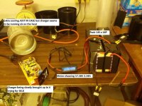
I am in the process now of charging a 14S pack and keep turning the pot a little more
each time the charger kicks off saying it is fully charged.
I'm up to 58V still @ 2.4A
Will let you all know if & when I hit my 58.8Min V target.
It will take a while as the packs I make are 14 square 14P x 14S with Panasonic CGR18650DA 34.3 Ah total
Thank you ALL for helping me with this.........I have 10 of these chargers I was going to have to replace as I am staying with 14SXP square packs for my Trikes.
small charger44.jpg
Will start new thread but here is idea
Type 1 front drive
IMG_20150726_145527.jpg
Type 2 Rear drive
IMG_20150726_144827.jpg
IMG_20150726_152129.jpg

Thanks again to ALL
 
You can save a lot of time if you measure the voltage on the non-switched side of the relay, like Dnmun suggested.
 
You be right about that got instant reading....cranked to 58.8V Done
 
Status
Not open for further replies.
Back
Top