
Hi,
I'm building a battery pack using these batteries: http://www.hobbyking.com/hobbyking/store/uh_viewItem.asp?idProduct=26664
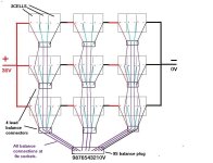
I've been using them with 3x in series, making 36V, and they have been working ok. I've just received a 1000W balance charger, so now I want to parallel 3x 3x in series batteries making a 27Cell pack.
You can see there are balance leads on each battery. I want to make some leads for balance charging, terminating with one large one for the charger socket. See attachment. I want to leave this set-up when riding, is this ok? I understand that if any cells are out of balance, the balance leads will be taking the current, so I will add resistors, are there suggestions for the resistor value please?
Camerart. EDITED IMAGE
I'm building a battery pack using these batteries: http://www.hobbyking.com/hobbyking/store/uh_viewItem.asp?idProduct=26664
I've been using them with 3x in series, making 36V, and they have been working ok. I've just received a 1000W balance charger, so now I want to parallel 3x 3x in series batteries making a 27Cell pack.
You can see there are balance leads on each battery. I want to make some leads for balance charging, terminating with one large one for the charger socket. See attachment. I want to leave this set-up when riding, is this ok? I understand that if any cells are out of balance, the balance leads will be taking the current, so I will add resistors, are there suggestions for the resistor value please?
Camerart. EDITED IMAGE
")
