BMS Bypass for Serial Voltage Increase (36v x2 for 72v)

Joined
Sep 8, 2019
Messages
462
Location
USA, CA, Bay Area
I've got a matching set of "vintage" A2B battery packs (downtube and rear rack). The cells are super old and tired (10 and 13 years old) and I'd like to replace them. They are traditionally NOT wired in parallel (each has a separate charge port) -- in fact, the whole schtick of the bike was a key switch to flip between batteries. Each pack is a 10s3p and have a built in BMS along with dedicated charge port.

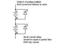
While I'd like to keep them (mostly) built in their stock config (36v wiring, BMS'd as normal, and can be charged by 36v charger) I do want to run a 72v system. Normally when this is brought up the threads talk about needing to make sure each BMS won't freak out because you're passing the higher voltage across the second pack and needing to deal with one/both of the BMS individually dropping out, etc. Specifically, this all hinges on wiring the packs in series going through the individual BMS(s), i.e.:
through-bms.jpg

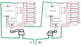
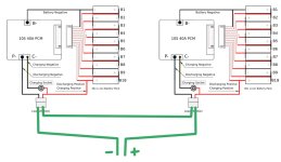
I'm curious about a different route: pull wires out from each pack that are directly connected to the pos/neg cell ends so I can wire up a 72v series connection bypassing the individual BMS(s). i.e.:
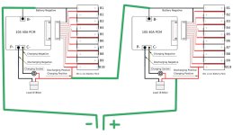
bypass.jpg

I'm aware this would remove bms level protections; a risk I'm willing to accept (or perhaps work around with some other warning system if the BMS load pathway is opened).

Would there be risk to the BMS(s) in such usage? Or, because current/voltage for the controller isn't actually flowing through the BMS(s), this will act fine?

I just don't want to risk the BMS(s) as these are very bespoke and would be hard/impossible to replace with a generic BMS if I blow them up. (In case of uncertainty I'll just disconnect the BMS(s) entirely to avoid any issues, but having them present to handle charging/balancing sure would be nice.)
 
If you put them in series like the first drawing, if either one trips, it will put the combined voltages across the tripped BMS and probably blow it up. Not recommended. There is a way to place big diodes across each BMS output to prevent over voltage if one trips. This is an option.

BMS in series config.jpg

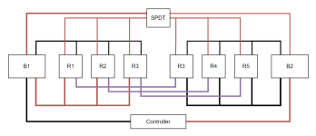
In the second drawing, you could do it that way. If you could power the relays from the normal BMS output, the relay would open and kill power, protecting the pack. The relays can handle 72v on the contacts. It might be hard to do both packs to the relay but easy to do one.

I don't think the stock A2B controller will take 72v, but I've never tried it. Most likely 63v rated caps. I ran mine for over a year on 52v with no failures. I did overheat the motor a couple of times and had to wait 30 minutes for it to cool off enough to reset.
 
fechter said:
If you put them in series like the first drawing, if either one trips [...]

For sure, not the plan. (One of your posts showed up on this topic ;D)

fechter said:
In the second drawing, you could do it that way. If you could power the relays from the normal BMS output, the relay would open and kill power, protecting the pack. The relays can handle 72v on the contacts. It might be hard to do both packs to the relay but easy to do one.

I was actually thinking about that, trying to recover that original protection level. Each BMS output could power a relay and just run them in series, or have one interrupt the neg the other the positive. One of these setup something like this:

relayed.jpg

fechter said:
I don't think the stock A2B controller will take 72v, but I've never tried it. Most likely 63v rated caps. I ran mine for over a year on 52v with no failures. I did overheat the motor a couple of times and had to wait 30 minutes for it to cool off enough to reset.

Oh lord no; that controller is in the bin already.
 
Those relays should work fine. You'll need a way to turn the relays off. A SPDT switch could do both at the same time.
 
fechter said:
You'll need a way to turn the relays off. A SPDT switch could do both at the same time.

Why? Wouldn't they simply be going on/off because the each BMS is or is not supplying voltage? The coil side would be activated by the BMS allowing 36v power out of the battery, closing the load side allowing the 72v flow to work. If one of the BMSs decided "something is wrong" and shuts down the BMS output, the relay would open and the bike power would shut off.

(I think I'd also need a two or three of these in parallel to support more than the 40A load each can handle individually.)
 
This thread about using contactors driven by the BMS output may be useful:
https://endless-sphere.com/forums/viewtopic.php?f=2&t=117973
and this post over here:
https://endless-sphere.com/forums/viewtopic.php?f=2&t=117890#p1735095
 
chuyskywalker said:
Why? Wouldn't they simply be going on/off because the each BMS is or is not supplying voltage? The coil side would be activated by the BMS allowing 36v power out of the battery, closing the load side allowing the 72v flow to work. If one of the BMSs decided "something is wrong" and shuts down the BMS output, the relay would open and the bike power would shut off.

(I think I'd also need a two or three of these in parallel to support more than the 40A load each can handle individually.)
You need a way to turn them off when you're not using the bike. Otherwise they will drain the batteries.

The stock BMS has a 40A fuse on it. A 40A relay should be fine. More than that will trip or blow the BMS.
 
fechter said:
You need a way to turn them off when you're not using the bike. Otherwise they will drain the batteries.

Ah, duh :)

fechter said:
The stock BMS has a 40A fuse on it. A 40A relay should be fine. More than that will trip or blow the BMS.

The current won't be flowing through the BMS(s), though.
 
Well that got more complicated than I thought going into this :D

2022-10-17 20_51_36-Window.png

I was considering building the packs up with molicels and running up to 100 battery amps, hence the 3 relays @ 40A. There are certainly larger relays, but they also start getting bulky quickly.
 
amberwolf said:
You might check out the contactors in that linked thread. ;)

>.<

Alright, so not much bigger it turns out. (I had looked at this on the batteryhookup site, but was hard to understand size with nothing to compare to...)

That model would need a step down though since it uses 9-36v to close (not up to the 10s 42v max level). Any idea what happens when you overvolt a coil like that?
 
One of the two linked threads discusses how to use a resistor (like controllers do) to drop enough voltage to limit coil current to normal levels. Ignore the first math post; I screwed up the formula; :oops: the second ought to be correct though.
 
Back
Top