
You are using an out of date browser. It may not display this or other websites correctly.
You should upgrade or use an alternative browser.
You should upgrade or use an alternative browser.
Bottom balancing?
- Thread starter morph999
- Start date
dnmun
1 PW
this is why i keep telling people to put a big power resistor on the cells to speed it up. those are big batteries. when it shuts off how far does the voltage drop before it turns on again?
izeman
1 GW
@pohjeremy: whatever you choose to use - i REALLY recommend to use any plug that can NOT be connected in reverse. banana plugs are the same for plus and minus. use dean connectors, xt60 are something like that to be safe.amberwolf said:You could indeed just add a socket (banana jack, if you wish) at each junction between seriesed cells, plus one each at the top and the bottom of the pack. Then connect the single-cell charger across any of them that aren't fully charging.
all of my batteries are totally fool proof. no chance on connecting anything to where it doesn't belong for all connections that are to be connected and reconnected more than once (other than for initial installation).
dnmun
1 PW
from the looks of it you will have it balanced by now. if you have 30S of cells then you want the final charger voltage to be about 108V-110V. 108 is best for longevity, 110 will give you an extra 1-2% of power but above 3.65V it is hard for the lifepo4 to store much more charge. above 3.60V the lithium wants to plate out away from the anode. but that is secondary.
you will see that the high cell cannot go high any more because all of the other cells have climbed in voltage so there not much excess voltage left to remain on the high cell so it drains off to match all the others.
once they have all charged to full voltage and the BMS has allowed them to stabilize around 3.60V then you will be able to charge them and discharge them and the voltages will track together now and you won't have a problem with that #5 cell being way high from the others.
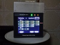
The last I saw (hrs ago), slave 2's lot....cell 15-30, not yet...near 3.3x, maybe 2 @ 3.40x.
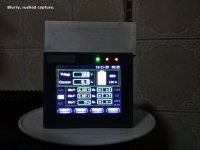
Then the jack for display suddenly died a few hrs ago....changing it now.
***********************************
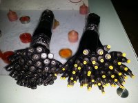
izeman...thanks, will consider..
though only for near 3.65V 4A...thus chose those 18ga bananas...
already bought..
quality appears ok...and tested on 2 spare cells (CA60)...seems ok, 1 mth..
u still think I shld reconsider..?
Hey, thanks...appreciate your continued objectivity.")
(see pic)
Then the jack for display suddenly died a few hrs ago....changing it now.
***********************************
izeman...thanks, will consider..
though only for near 3.65V 4A...thus chose those 18ga bananas...
already bought..
quality appears ok...and tested on 2 spare cells (CA60)...seems ok, 1 mth..
u still think I shld reconsider..?
Hey, thanks...appreciate your continued objectivity.
(see pic)
Attachments
izeman
1 GW
ok. if that is what you have you're good to go from a error free environment. the yellow one will be installed on the battery so you can't short the contacts by accident.
regarding the current i don't know how much those connectors can handle. 18awg is ok for 4a.
this is what i meant with banana plug:
the yellow one will be installed on the battery so you can't short the contacts by accident.regarding the current i don't know how much those connectors can handle. 18awg is ok for 4a.
this is what i meant with banana plug:
izeman
1 GW
nono. those are charging adapter. the correct stuff to use.
Hi dnmun and all,
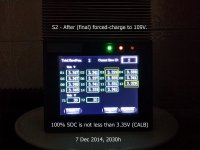
After 9 days of trying to balance the old CAM60Fls...I seriously give up.
(At least several) slave 2's cells just do not rise...from the first....no matter how high slave 1's cells do....regardless of balancing mode or forced-charge mode to 109V.
My attention now turns to the newly arrived cells. I need to get it right this round.
Attachments

dnmun
1 PW
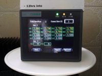
what is S2? you should see if your display will tell you how much current is flowing into the cells in S2 during charging.
if it is part of the battery you charged to 108V then it should eventually store more charge and the cell voltage will climb then.
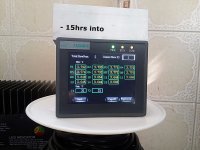
if all of the cells in the S1 section are at high voltage you can use a large power resistor across all of those cells to drain charge off as you continue charging to bring the cells in S2 up to full charge. you can even use a light bulb for the load to drain the charge off of S1.
if it is part of the battery you charged to 108V then it should eventually store more charge and the cell voltage will climb then.
if all of the cells in the S1 section are at high voltage you can use a large power resistor across all of those cells to drain charge off as you continue charging to bring the cells in S2 up to full charge. you can even use a light bulb for the load to drain the charge off of S1.
dnmun
1 PW
this needs to be fixed before you start working with the new cells because all of this is totally new to you. there is something wrong if that second section S2 is not receiving charge. those cells in S1 should not be taking 10A either since they are fully charged. i do not know how you came up with the 10A number but i doubt if any current is flowing out of the charger at all while all those cells are at the HVC. maybe once you drain the charge off of that section the charging will restart.
Ok, erm...I don't intend to use that bulky Canbus BMS on the new cells or pry open the old casing to meddle with the connections of a Canbus BMS I did not install...and could have been installed wrongly.
This might offend you but in fact, I don't even intend to use a BMS on the new cells.
This might offend you but in fact, I don't even intend to use a BMS on the new cells.
dnmun
1 PW
that is just because you don't know anything yet. all of the newbies act like they don't need a BMS. most of us don't have that kinda money to throw away. especially to the chinese army.
Per your notes on the image itself, then yes, step 1 is to parallel connect all the - of all cells together, and then separately connect all the + of all the cells together, with no other connections between the cells.
That will force any high cells to discharge into any low cells, and they will all end up with the same final voltage, and assuming they are all matched cells they will also then all have the same amount of charge (capacity) in them, too.
If they are matched cells and are of good quality, then until they begin to age significantly, they should stay in balance pretty well (unless they are discharged down too far, like down to the bottom of their capacity; that appears to be what tends to unbalance most of the packs I've seen problems with so far, that didn't have to do with defective cells or physical damage of some sort, or workmanship issues).
You could indeed just add a socket (banana jack, if you wish) at each junction between seriesed cells, plus one each at the top and the bottom of the pack. Then connect the single-cell charger across any of them that aren't fully charging.
However, without some sort of cell-level monitoring system (even if it doesn't balance things), you have to "know" the capacity of your pack, and be sure to never exceed it, and also to retest things periodically to be sure they are still in balance at various states of charge (if they're not, then you may have cell(s) that are lower capacity than others, and then you have to remember that lowest capacity is your pack's maximum capacity so you don't overdischarge that cell).
Amberwolf, best stuff! Thanks.
Gab said:what about cell drift with no BMS ?
Can't seem to log CELL DRIFT data as yet nor do I know how to. Perhaps someone can illuminate.
I do not want a BMS due to the lack of space and trust for reliability...those small parts; Lack of time to test several (e-bike/motorbike-sized) BMSes, then settle for a trusted vendor...at least in this part of the world. I've spent several years doing that w a controller and motor. Finally found more trustworthy manufacturers.
So back to the Batt selection.
What I did was this to 'hopefully' minimize assembling a 'bad' cell:
- had been hounding the company to provide cells that have near equal OCV, Ah, IR...the IR might too insignificant....and make them prove it (to a certain extent).
- testing self-discharge now. excel results out soon.
- then select (need advice).
- then parallel-balance them at what V that maybe u can further illuminate me...3.250? 3.350? 3.275? 3.600? So many diff opinions here! I value them all...?
- will install 15mA voltmeters and individual charging jacks for each prismatic, apart from the bulk charging option.
- will monitor HVC and LVC of each cell closely, manually.
- pls advice..
Hey, thanks.
dnmun
1 PW
not opinions. i tried to educate you. when he asked about drift he was asking you why you do not account for self discharge of the lifepo4 cells. stuff you just do not know about. but that is why nobody uses bottom balancing. i do not understand what you meant about demanding all this new information from your supplier about the lifepo4 cells you bot.
i never did understand why you scrapped all those brand new 66Ah CALB cells. all this is just way over my head.
i never did understand why you scrapped all those brand new 66Ah CALB cells. all this is just way over my head.
dnmun said:not opinions. i tried to educate you..
Yes, THANK YOU...I hope you would still.
Solcar
10 kW
I was contemplating how to best keep dealing with my lifepo4 batteries as simple as I could and found Jack Rickard's ideas seeming to make sense as I was looking on the Web for ideas. He says that the battery pack of series cells is limited by the weakest cell, so the best way to use lifepo4 packs is to bottom balance and when using the battery, stop discharging when the weakest cell drops to the determined value. The bottom balancing makes the whole pack drop more with the weakest cell, which makes it easier to prevent damaging it or other cells because the discharge drops the series voltage more. It is easier to watch the battery status. The way he explained it makes sense as far as I can see.
dnmun
1 PW
except he knows nothing about batteries. you should always use the battery at full charge since there is lower internal resistance to the movement of the ions through the battery.
if you use the battery at the lower part of the charge then it constantly is pushing current through a battery with much higher internal resistance.
there is no reason that you should not charge your battery to full charge. the hysteria over fully charging a battery is uninformed and misplaced on a bulletin board dedicated to providing accurate information. evtv can do what they want because he has no such responsibility.
999zip999
100 TW
All battery chemistry's act different in balancing and different lifepo4 cells act different when charging and balancing.
So what lifepo4 cell are we talking about and for what use. So what demands are you putting on the battery. Charging and discharging. Makes a big difference in balancing. We need the whole picture.
So what lifepo4 cell are we talking about and for what use. So what demands are you putting on the battery. Charging and discharging. Makes a big difference in balancing. We need the whole picture.
Solcar
10 kW
999zip999 said:All battery chemistry's act different in balancing and different lifepo4 cells act different when charging and balancing.
So what lifepo4 cell are we talking about and for what use. So what demands are you putting on the battery. Charging and discharging. Makes a big difference in balancing. We need the whole picture.
My battery is a 40 amp hour Thundersky lifepo4 that has 4 cells. I want to use it on my latest ebike project, a friction drive that I built from scratch. I'm expecting to not tax the battery a whole lot, and I want the battery to require as little monitoring and handling as possible. It is rated at 80 amp discharge, but I plan to stay well under that figure.
The motor that the battery is powering is a small brushed type. It was rated 2800 rpm at no load at 12v. It also was rated as producing a stall torque of 216 oz-in. I plan to boost the battery voltage by means of the controller I'm making to get more power out of the motor, which nominally is in the 100 watt category at 12v. It's a good quality Pittman motor and I expect it can take many times that voltage so long as the current is kept down. That could produce at least a few hundred watts.
On my last ebike project, which was a through-the-gears type, I was taking the motor voltage to around 40, but with current limiting. Since it was through-the-gears, the way it worked out was that it basically could push the pedals with a force approximately equal to 2/3 that of my legs under moderate effort, no matter how fast I was pedaling. I didn't have a freewheel on the chainring, so I eventually decided that my next project would allow pedals to be independent and not have to turn during motor assist. This third friction drive project should provide that, as well as freewheel itself when it isn't under power.
Similar threads
- Replies
- 7
- Views
- 412
- Replies
- 10
- Views
- 497
- Replies
- 7
- Views
- 338