Broken Controller - Crystalyte CT4840

Joined
Apr 1, 2013
Messages
35
Location
Colorado Springs, CO
Hello All,

I'm somewhat of a newbie here. I have a Jamis Dakar fitted with a Phoenix/Crystalyte x5303 motor (1st generation with no disc brake). A couple months ago, I stupidly tried to climb a sidewalk curb from a stop and broke something within the Crystalyte x5303 motor. :oops: I remember that as I was trying to climb the curb, the motor hesitated for a moment before giving out. Not good.--It was followed by the dreaded walk of shame back to the car. :( Anyways, now I'm looking to ES for some pointers as to how to start diagnosing the problem so I can get it fixed.

In its current state, the symptoms are as follows:
When throttle is twisted, the motor or control makes a "click" sound but nothing happens.
The rear wheel is locked up/hard to turn.--When riding, it wobbles and has quite a bit of resistance.

I have since pulled the motor out of the hub casing and it is ready for testing. Feel free to provide some pointers as this is all new to me.--or if there are any threads you can reference, that works as well.
 
If the wheel has a significant amount of resistance (more than the normal resistance of the X series motors), that would imply that some of the phase wires are shorted together.
Now inside the motor, the phase lines are wired together anyway at the wye (coil configuration). But to test if the short is inside the controller instead, re-mount your hub motor, unplug the phase wires from the motor, and try and rotate the wheel by hand. If it spins freely as it would normally do, then the problem lies within the controller. If not, then there may be something wrong within the motor.

The "click" you describe sounds like a hall sensor problem. Does the motor at least try to turn i.e. shudder back and forth? When a hall sensor fails, the controller doesn't know whereabouts the motor is in its rotation, and doesn't know which coil to fire next, thus resulting in shuddering. It also causes the motor to shudder during regenerative braking (as I found out the hard way).

To test if the hall sensors are working properly (and assuming you have a multimeter), follow the instructions here:

http://www.ebikes.ca/troubleshooting/HallSensorTestingFinal.pdf

In case it's the throttle that is the problem, you can test it following the instructions here:

http://www.ebikes.ca/troubleshooting/ThrottleTesting.pdf

Because you tried climbing a kerb from a standing start, I'm guessing you were giving it full throttle while the motor was barely turning? If so, all that electrical current gets put into a single coil, and with no way to exert the energy (i.e. by making the wheel spin), it backfires and could have blown MOSFET's in your controller.
The old X series motors are built pretty rugged and the copper coils themselves are fairly unlikely to burn out.

To test if the MOSFETS in your controller are working, follow the instructions here:

http://www.ebikes.ca/troubleshooting/BlownMosfets.pdf

That's the basics anyway. I'm actually diagnosing my X5304 right now due to a recent failure.

I hope this helps!
 
Since the 5303 is notorious for blowing controllers, my money is on blown fets in the controller. What you did, is how you blow one too. A pretty noticeable wobble may just be normal for those older clytes.

I have found the 30 bucks I spent on a motor controller throttle tester to be the best money I ever spent on ebike stuff. Makes detecting a bad controller or burnt out halls a snap.
 
All, thanks for the help. I will try to take all into account. See below notes.

dogman said:

@dogman
Where do I buy one of these motor controller throttle testers? Any reccomendations on brand or type?

TheThirdWheel said:

@TheThirdWheel
I will try all of your tests, it will take me some time. I have to go find my multimeter first---and then test away. :)
As far as the "click", the bike makes barely any movement. It is more of a hesitation and I don't believe the wheel turns at all. I will have to re-assemble to confirm but this is the way I remember it.

999zip999 said:

@999zip999
Not sure if I get what you mean here...Are you saying that Drkangle has this tester available for sale? Can you reference the link to his thread.
 
I tested hall sensors as TheThirdWheel stated in his post. Using that PDF file (http://www.ebikes.ca/troubleshooting/HallSensorTestingFinal.pdf) The first part of the step where I test the voltages on all of the wires, all of the wiring reflected voltage readings of between 4-5 volts as needed except for the BLUE wire. This one showed 0 volts. How do I proceed from this step? I'm assuming now I have to disassemble the motor to gain access to this hall sensor in order to replace it.

Thanks for the help

(By the way, the motor clearly makes a single "click" sound upon startup--i.e when turned on)
 
If your blue wire won't toggle between 5v an 0v as the wheel is rotated, then the hall sensor is bad. If your test didn't include rotation, then the hall might just be turned off, till it rotates and turns on.

Take apart the motor to get to the hall sensors and replace the bad one.
 
I went back and tested by turning the wheel slowly. All three wires switched back and forth between 0 and roughly 4.84 volts--or thereabouts. I guess this rules out the halls sensors. Moving on to the test the MOSFETs in the controller...

In the meantime, I am waiting on the brushless motor/controller/throttle tester I bought as previously referenced here:
Drkangle Bargin Toolbox Thread - http://endless-sphere.com/forums/viewtopic.php?f=2&t=47924
Accompanying Testing Intructions shown here - http://endless-sphere.com/forums/viewtopic.php?f=31&t=20413&hilit=Electric+Bike+Controller%2FMotor%2FThrottle+Tester&start=15#p307438

dogman said:
If your blue wire won't toggle between 5v an 0v as the wheel is rotated, then the hall sensor is bad. If your test didn't include rotation, then the hall might just be turned off, till it rotates and turns on.

Take apart the motor to get to the hall sensors and replace the bad one.
 
coloradoebiker said:
I went back and tested by turning the wheel slowly. All three wires switched back and forth between 0 and roughly 4.84 volts--or thereabouts. I guess this rules out the halls sensors. Moving on to the test the MOSFETs in the controller...

Sounds like the hall sensors are functioning normally. Now you just need to check the MOSFETs using the method in the link I provided earlier.
If it all seems fine, then you're in the same boat as me i.e. everything says it should work, and yet it doesn't (recently dead Infineon controller).
Currently waiting on my ebike tester!
 
Oh, just a note: If you get readings of 0 ohms on the MOSFETs, try reversing the multimeter probes. I found that with my setup, I get 10KOhm one way, then when I probe the same wires with reversed multimeter leads, I get 0! I don't know if this is normal though..
 
So I finally received my ebike tester from China. Its looks pretty shoddy but anyways, I don't get how to hookup this thing to test to see if I blew the MOSFETs within the controller. See below pictures to see what I have to work with. Can anyone point me in the right direction?

thanks

E-bike Tester:
EbikeTester.jpg


Cables/Wiring Connections:
CablesandWiring.jpg


Controller:
Controller.jpg
 
Hook the left side for the controller. Forget about the throttle hookup as this is for the controller . The three aligator clips are for phase the five pin is for the halls than hook up the battery and twist throttle.
 
Total noob here....Don't quite know how this works but it seems that the connectors don't match up as I have a first gen Crystalyte??

999zip999 said:
Hook the left side for the controller. Forget about the throttle hookup as this is for the controller . The three aligator clips are for phase the five pin is for the halls than hook up the battery and twist throttle.
 
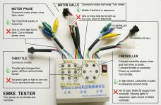
To test the motor, connect the motor hall phase wires to the ebike tester leads marked "motor coil". It doesn't really matter what order you connect them in, but you can colour match if you want. After this, give the motor a spin (fairly fast). The lights labelled "A(yellow), B(green), C(blue)" next to "coil" should flash in sequence as the motor spins. You will have to spin the motor fast on these old Crystalytes.
You don't even need to have the tester switched on. As long as all 3 lights light up, AND don't light up at the same time, the motor phase windings are fine.

Next, you can disconnect the phase wires from the tester, or leave them on. It doesn't really matter. But now you need to connect the motor hall sensor lead to the tester using the leads marked "motor hall signal wire". Again, it doesn't matter what colours you connect to other colours EXCEPT red and black! The red must connect to red and the black to black.
The plug on the ebike tester will most likely be different to the plug on your ebike so you can either back out the pins in the plug and connect it all up using alligator leads like I did, or solder your own plugs on.

Once connected, power on the tester (provided you have a 9V battery in it) and give the wheel a spin. You should see all 3 lights next to "Hall signal" light up in sequence on the tester.

To test the controller, connect the phase wires of the controller to "controller main wire", again the colour order doesn't matter. Also connect the controller hall sensors to "controller hall signal wire", once again modify the plug if you have to. Again I remind you that RED connects to RED and BLACK to BLACK! The other 3 colours can be mixed.
Also, connect your throttle to the controller, and the controller to your battery.
Switch on your controller and apply a small amount of throttle and hold it steady. The lights around the "5V" on the tester should be switching on in adjacent pairs.
Usually the ebike tester shows one loop of flashing lights, then stops. Just let go of the throttle and re-apply it again to verify the test.
If lights fail to come on, or opposite lights switch on at the same time, then there is a problem in the controller.
 
you can test the mosfets in the controller with your DVM.

use the diode tester to test the mosfets in each phase on the hiside and the loside.

the mosfets are between the B+ and the phase called the hiside, and between the phase and the ground B- called the loside.

these are n channel mosfets so the drain is connected to the higher voltage lead in each case.

for the hiside, use the diode tester and put the red probe on the red wire to the controller, B+, and then test each of the phase wires with the black probe. they should all read open circuit.

then reverse the leads and put the black probe on the B+ controller lead and test each phase wire with the red probe and you should see the body diode, about 400mV.

do the same thing for the loside. put the red probe on each of the phase wires while the black probe is on the ground B- lead of the controller. all phases should show open circuit.

then reverse the leads and put the red probe on the ground and the black probe on each of the phases. they should show the forward bias of the body diode, about 400mV.

record all the numbers for hiside and loside so you know which phase is shorted.

you do not need the ebike tester thingy.
 
Instructional tester HowTo PDF here.

Outfitting your tester with longer wires and mating connectors for your particular controller/motor/throttle is a bit of a PITA, but reduces test time to just a few minutes. Worth the effort.
 
Hello 999zip999,

I decided that I really hate having to back out the wires and use extra alligator clips as this would become a mess real fast. I will be picking up a male 5-pin XLR connector during my lunchhour today so that the hall wires of the tester can be adapted to the xlr connecter on my ebike setup. Thanks for all the advice/help guys. I will report back on the results in the next few days

999zip999 said:
What's going on ?
 
i thought you had tested the hall sensors already. you don't need any special tools, just use the diode tester on your DVM to see if the mosfets are functional. that is what is broken and you just need to identify which ones are bad. i gave a complete step by step procedure which should be easy enuff to do in about 2 minutes.
 
This may help.
E-bike-testerezguide.jpg
 
Ok all, so I did finally tested the controller using the tester. It took awhile since I wanted to adapt the mini XLR connectors so I had to order those. Anyways, I made a video of what the tester shows. I'm guessing I will have to tear the controller apart and locate whatever part(s) I blew. Let me know what you guys think my next step should be.

https://www.youtube.com/watch?v=VTeRe9CRJbE
[youtube]VTeRe9CRJbE[/youtube]
 
Back
Top