C300-LCD Instructions

otool

1 µW
Joined
Sep 30, 2023
Messages
4
Location
Colongne
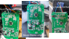
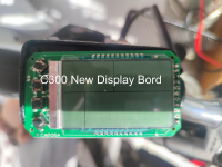
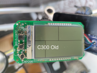
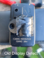
Hello Members and support, I have two C300 displays one display with the platineboard CAP09R and the other board is CAP05A and now my request to you, can you please help me to find out the pinout for the conversion from old board to the new , I have the problem that the new pinout is different and is not identical to the old C300 display.

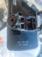
Attached you will find several pictures that show which boards I have and how the wiring is.

Now I hope that you can help me as soon as possible.


With kind regards from Germany

Guido Wander
 

Attachments

  • Untitled.png
    Untitled.png
    3.5 MB · Views: 21
  • C300-New.png
    C300-New.png
    577.4 KB · Views: 20
  • C300 Old.png
    C300 Old.png
    522.2 KB · Views: 18
  • IMG_20230926_095210.png
    IMG_20230926_095210.png
    578.7 KB · Views: 16
  • new display_1.jpg
    new display_1.jpg
    115.7 KB · Views: 17
not an engineer, but this is how i see it..
Both red wires connect to B, Black on one and white on the other are connected to G.
(B? for Battery, G? for Ground)

I therfore suspect B=vcc and G = Ground. should be easy to confirm with a meter by turning the bike on. and testing continuity with components on the pcb (with power off) for example many if not most capacitors will be grounded on one side so should show continuity with G

with Vcc and G identified we can assume the other wires are data and signal wires so safe to swap and test..

cant you check which wire is which from the connector to the controller or is it a sealed socket? continuity can still be used to determine which pin is connected to which wire, if its a Female socket? then the snipped leg of a resistor or capacitor is the ideal size to make a test probe

I suspect the different wiring may be the way different coms protocols are selected? but that may not be the limit of the changes needed?
That is great information, I have another call with qwick on Monday and hope they will send me a manual for the two C300 displays because they are through a supplier I believe that is from bigstone-nj.com and I'm sure they still have the schematics for the individual boards.
Your information is already clear to me, but I need the correct pinout from A to K. I think this is the way to go.
But I will report and show you my way to the goal.

guido
 
this is my wiring harness and control module which is built into the bike and has been connected to the old display C300C-1301A0126 QWICK 36v.
 

Attachments

  • IMG_20230929_210128.jpg
    10.2 MB · Views: 16
  • IMG_20230929_210212.jpg
    8.1 MB · Views: 16
That is great information, I have another call with qwick on Monday and hope they will send me a manual for the two C300 displays because they are through a supplier I believe that is from bigstone-nj.com and I'm sure they still have the schematics for the individual boards.
Your information is already clear to me, but I need the correct pinout from A to K. I think this is the way to go.
But I will report and show you my way to the goal.

guido
this is my wiring harness and control module which is built into the bike and has been connected to the old display C300C-1301A0126 QWICK 36v.
 
Back
Top