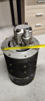
I recently got my hands on a forklift DC motor, papers that came with it say that it is capable of 10kW @ 75V and 165A at 2800rpm.
Weight is 44.7kg.
Tested it a bit with car battery, seems to work alright.
As it is oil pump motor, it only has 2 terminals and always rotates same way.
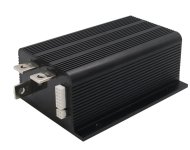
Now, to get it running properly I ordered a Curtis P1253-8001 from eBay, so most likely a chinese copy of real thing.
This is made exactly for oil pump motors and should be relatively simple.
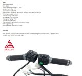
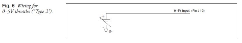
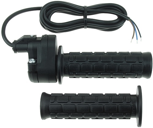
It is supposed to do 80V and max 600A. Throttle type I ordered was 0-5V.
Now the thing is that I cannot get the controller to do its duty.
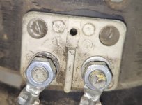
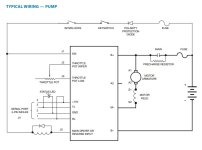
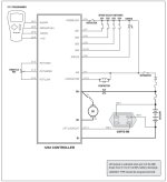
I made the connections according manual - battery to B- and B+, motor one pole to M-, other pole to B+.
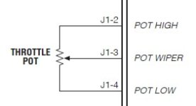
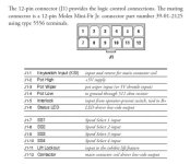
Also throttle is connected to pins 2-4 and LED light between to pin 6 and 1.
Now there is the KSI pin1 which should power everything up.
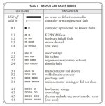
When I connect it, the only result I seem to get is blinking code of 3,2 - welded main contactor. And I do not even have a contactor.
Tried connecting a 72V relay coil between pins 1 and 12 but that did not change anything. The relay did not work and error code is the same. Neither did connecting pin5 - interlock or pin11.
Contacted the seller who supposedly tried asking from manufacturer but got nothing back and refunded entire thing.
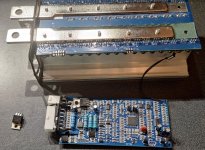
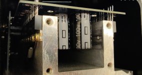
After that I opened controller from back to check the internals and as far as I can see it looks quite solid.
So maybe it is not completely hopeless but just needs some kind of special connection to get past this welded contactor?
I am all out of ideas and it does not seem to be very popular controller too as there is next to nothing about it in internet.
Also tried to get software access to it through DIY programming cable but also nothing.
Can anyone point me the right direction?
Weight is 44.7kg.
Tested it a bit with car battery, seems to work alright.
As it is oil pump motor, it only has 2 terminals and always rotates same way.
Now, to get it running properly I ordered a Curtis P1253-8001 from eBay, so most likely a chinese copy of real thing.
This is made exactly for oil pump motors and should be relatively simple.
It is supposed to do 80V and max 600A. Throttle type I ordered was 0-5V.
Now the thing is that I cannot get the controller to do its duty.
I made the connections according manual - battery to B- and B+, motor one pole to M-, other pole to B+.
Also throttle is connected to pins 2-4 and LED light between to pin 6 and 1.
Now there is the KSI pin1 which should power everything up.
When I connect it, the only result I seem to get is blinking code of 3,2 - welded main contactor. And I do not even have a contactor.
Tried connecting a 72V relay coil between pins 1 and 12 but that did not change anything. The relay did not work and error code is the same. Neither did connecting pin5 - interlock or pin11.
Contacted the seller who supposedly tried asking from manufacturer but got nothing back and refunded entire thing.
After that I opened controller from back to check the internals and as far as I can see it looks quite solid.
So maybe it is not completely hopeless but just needs some kind of special connection to get past this welded contactor?
I am all out of ideas and it does not seem to be very popular controller too as there is next to nothing about it in internet.
Also tried to get software access to it through DIY programming cable but also nothing.
Can anyone point me the right direction?
")