can't make Turnigy ESC with thumb throttle work

vanagreg

1 µW
Joined
Aug 10, 2020
Messages
4
Hello,

I'm all new to this so bear with me silly questions or lack of knowledge of the RC world.
I've been building a stand-up e-scooter from an Oxelo scooter and have managed somehow to assemble all the parts together. To handle the speed I used the servo tester coupled to a thumb throttle. I use the following topic as a guide:

https://endless-sphere.com/forums/viewtopic.php?f=28&t=12196&start=175#p1278793

I did the same wiring but when I tried to use it with the ESC it doesn't work, or I don't know how to do it properly maybe. The ESC is this one:
https://hobbyking.com/fr_fr/turnigy-brushless-esc-85a-w-5a-sbec.html

The manual can be found here:
https://cdn-global-hk.hobbyking.com/media/file/t/u/turnigy_85a_esc.pdf

So I thought I only had to calibrate it to make it work (page 8 ), but I don't get the beep I'm supposed to get. Here's what did:
- Push the thumb thottle to the max
- Plug the battery to the ESC
- Wait for 2 beeps (which does sound)
- Release the thumb throttle completely

--> Now I'm supposed to hear some beep to confirm the calibration has been done, but this where nothing happens.
If I hold the thumb throttle to the max for long, I hear all kind of funny beeps that are not even described in the manual.

I should point out that when I push the throttle to the max, the blue led on the servo is shown.
Would anybody know what's going on? Did I mess up with the servo wiring?
I can provide photos/videos if necessary.

Thanks
 
When you release the throttle does the pulse width stay above 1ms? The only ESC I ever messed with had a similar calibration at power up. After the full throttle of 2ms I had to release the throttle and it needed to see slightly above 1ms or it would fault. You may need to add resistors to the throttle to keep the pulse width output of the servo tester above that minimum the ESC is looking for (1ms).

An oscilloscope is pretty handy for checking things like this.
 
Hi Dan,

Thanks for replying. I have no idea about the pulse width as I have no way of measuring it (I don't have an oscilloscope or a multimeter with that measuring feature). So where should I place the resistor? What value?
In the meantime I've ordered another servo tester to test the ESC with the potentiometer.
I'll be in touch.
 
Here is a good read on tuning throttles with resistors if you are in the mood for a lot of info.

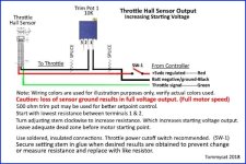
Post #3 has the elimination of dead zone portion with the picture of the blue 10k potentiometer. But this is the part I think you are looking for. In simple non scientific terms: Your clamping the ground a little with the resistor so the signal has to go through the output "green" wire. This effectively raises lowest voltage when the throttle is sitting at zero deg.
wfGeHkI.jpg

The problem you are going to have is that you really need an oscilloscope to know how many volts in to your servo tester equal how many ms you pulse with is. If you can't get a scope you are just going to have to guess.

Most ebike throttles I have seen are more like 1-4 volts. Measure the voltage out of your throttle between green and black. Install that trim pot and keep turning it up maybe .100 or .200 volts at a time. Each time go through the same power up process with your esc until the ESC gives you the right beep sequence you want.

I believe the esc wants the full throttle at start up to set the max then the value it drops to is what it considers zero throttle. I think your goal is to get this value close to 1ms but not under. Since the servo testers will produce pulses under 1ms I just think your voltage in from your throttle is not quite high enough.

Hopefully someone who has made one of these adapters will chime in. I only messed with one ESC and used a Cycle analyst in the place where you are using the servo tester.
 
Hi,

Thanks for the advice. I've received the new servo tester (exact same look and pins) and I could calibrate it without difficulty. After the 2 first beeps there was a long beep-short beep sequence when turning the pot to zero, confirming the calibration being done. And with this servo tester using the pot the motor does work, and it does it impressively fast I'd say! So at least I know both the ESC and motor work properly.
So I guess I'll have to get a pot to find the correct adjustement, right? I would appreciate if someone who faced the same issue would give me the proper value, or if there a thumb throttle yo guys know that works I could get it.

Thanks
 
Hi,

I wasn't sure about my first servo tester so I got another one and a hand throttle to do exactly the same as in this video:
https://www.youtube.com/watch?v=cceUTv6tAaA

In the video it works without calibration even needed, but in my case still no luck. Somehow the only thing I could achieve was the other way round, the motor working full speed when the throttle is released! So the motor goes full speed out of control. Is there something I can do to reverse that?
The next solution I'll try is using an Arduino board to do it programmatically. Never thought this would be so complicated. Everything is ready but this throttle bit, that's pretty frustrating!
 
vanagreg said:
Is there something I can do to reverse that?

If the throttle works well but opposite to what you desire. IE: you have good functional linear control, but with WOT operation with throttle released and nothing with throttle fully twisted or thumb lever pushed fully. You can reverse it's output by...
Turning the single magnet end to end, or by swapping both magnets in a 2 magnet throttle . Or by reversing which side of the throttle's hall sensor faces the magnet. Which ever is easiest...


DanGT86 said:
Here is a good read on tuning throttles with resistors if you are in the mood for a lot of info.

The diagram shown and more information on hall sensor throttles can be found here...
https://electricbike.com/forum/foru...r-throttle-operation-testing-and-modification


Regards,
T.C.
 
Back
Top