j bjork
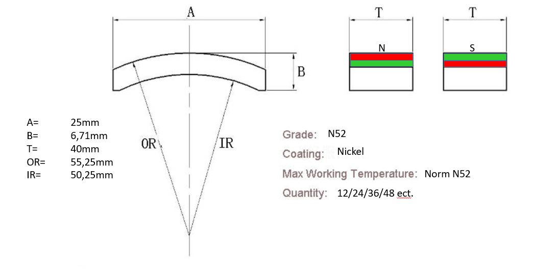
1 MW
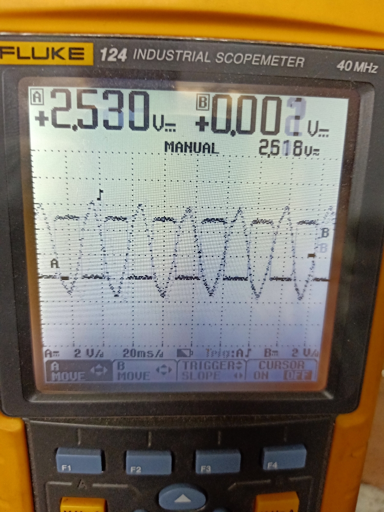
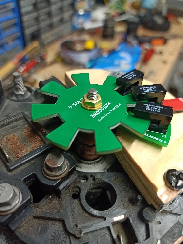
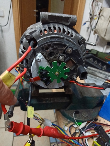
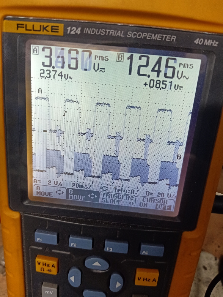
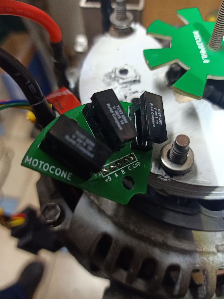
Another thing that seems strange is it seems to always want to spin in reverse. Every time I have set it up on the nuc it spins in reverse, but there I can just change direction. And I just connect the phases and halls in any order and run self learn.
On the cheap controller I have found a few combinations where it spins fine in reverse, but only bad running forward.
I might have missed some combination possibly, but it sure seems a lot harder to find a good forward combination.
On the cheap controller I have found a few combinations where it spins fine in reverse, but only bad running forward.
I might have missed some combination possibly, but it sure seems a lot harder to find a good forward combination.