Cell-Log Mod - Perfectly even drain! - FINISHED!

heathyoung

100 kW
Joined
May 27, 2009
Messages
1,545
Location
Newcastle, Australia
OK - Just a quick one.

I'm looking to use the Cell-Log 8's for a BMS - the one thing that is annoying me is that they have uneven drain across the cells. One member mentioned that they were seeing 100mV in 2 months, thats a bit ugly.

So - how to fix it?

You can mod the Cell-Log itself, but you remove the logging capability = FAIL

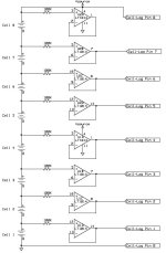
Or - you modify it to use rail-to-rail opamps, configured for unity gain, powered off the ends of the pack - the inputs of the opamps are basically infinite resistance (well, not really, but are far higher than anything else).

A quick search reveals a OPA1654AID is a 4 channel, unity gain, 4.5-36V single / dual rail opamp available in a SOIC14 package (about half the size of DIP). A quick sketch and transfer it to a PCB, bob is your proverbial. Its just a bit bigger than the footprint of a Cell-Log. The offset pin is used to select the last balance wire of the pack. Use wire links, or if you are OCD like me, use zero ohm 1/4W resistors. Yeah, I could have used double sided, but this is meant to be cheap and simple.

This will be used in the up-and-coming revision of the APBMS (Analysis Paralysis Battery Management System)

Feel free to steal it :)
 

Attachments

  • DrainEven_PCB_Copper.pdf
    5.2 KB · Views: 392
  • DrainEven_PCB_Silkscreen.pdf
    1.5 KB · Views: 260
Quiescent current (per channel) typically 2mA. 2.8mA worst case across the full temperature range.
8 channels * 2mA = 16mA.

Hours connected to drain 1AH = 1000/16 = 62.5 Hrs = 2.6 days.

And it's not rail-to-rail output. Typically (V+) – 0.8 (800mV).

Amanda
 
Can you show us all a photo of the finished article when you have one complete? Thanks Heath.
 
commanda said:
Quiescent current (per channel) typically 2mA. 2.8mA worst case across the full temperature range.
8 channels * 2mA = 16mA.

Hours connected to drain 1AH = 1000/16 = 62.5 Hrs = 2.6 days.

And it's not rail-to-rail output. Typically (V+) – 0.8 (800mV).

Amanda

Yeah I knew it was a bit thirsty, but should have read the specs better - might find another Opamp or an isolated dc converter to boost it a bit
 
Does the USB port supply power?
Could you just use a USB phone charger while connected to battery pack?
Could you disable the parasitic battery drain and use only the USB to power the board?
 
Nope, the USB port is used for power when you download the logs (not connected to a battery).

Its seriously irritating when a spec sheet says rail-to-rail, but it isn't. Means the top cell will measure low.

Actually... Now I think of it, you would just hook up the top cell to the Cell-log anyway. Opamp doesn't need to be rail-to-rail at all. Hmmm....

Awww yeah - LM224D, $0.24 each, 3-32V supply (enough for 7 series), 3mA for 4 amplifiers or a TL064CD, $0.48 each 7-36V (good for 8S), 200uA per amplifier (!!!). Easy.
 
I 'm not sure what you're trying to do here.

My experience is that even with the "even drain mod" that is popular here, the pack will still become disbalanced over time.

In my set up, I have a relay that controls the first pin on each cell-log, so I can power them all up when I switch the bike on. It's cool to switch on the bike, the cell-logs, and the thermometers with one switch!

BUT, after a month the packs are no longer balanced. Just sitting connected with the ground pin disconnected, the packs become disbalanced.

So, it looks like I'm going to have to manually switch each balance connector on and off with relays.

I'd love another solution, but I'm not to bright when it comes to this sort of stuff. Using relays is a caveman, option, but one I know I can make work reliably.
 
the USB does provide some power. Sometimes i use my cell log to check the voltage of my nimh AA batteries through a cheap plastic battery case rigged with balance taps and jst-xh connectors. (this allows me to use the ol hyperion to charge them also) Anyway if i dont attach a 5v usb adapter to the cell log the nimh would not provide enough juice on ports 1 and 2 (1.2v versus 3.7v) to get the cell log to come on. Hope this makes sense. I doubt powering the cell log with a 5v stops the drain on cells 1 and 2 though just supplements it.

Very much want you to succeed here Heath. even looked up unity gain after your first post since I'm not an EE. I have 4 bvm8s and one cell log 8s, at the moment im gonna rig 2 to the pack i ride 12s via 2x 18pin switches (they were cheap and its an easy way to be sure that there is no electrical connection without stressing the connectors by repetitively removing the cell logs all the time.) Still doesn't ensure that the cells wont drain even and thats what we need for monitored bulk charging.
 
auraslip said:
I 'm not sure what you're trying to do here.

My experience is that even with the "even drain mod" that is popular here, the pack will still become disbalanced over time.

In my set up, I have a relay that controls the first pin on each cell-log, so I can power them all up when I switch the bike on. It's cool to switch on the bike, the cell-logs, and the thermometers with one switch!

BUT, after a month the packs are no longer balanced. Just sitting connected with the ground pin disconnected, the packs become disbalanced.

So, it looks like I'm going to have to manually switch each balance connector on and off with relays.

I'd love another solution, but I'm not to bright when it comes to this sort of stuff. Using relays is a caveman, option, but one I know I can make work reliably.

This is exactly the problem I am trying to solve, I've experienced the same thing - they are a great adittion to a battery pack, but if they unbalance a normally balanced pack - this is a bad thing.

There are a few opamps that are not SOIC package if you wanted to try this - for example, TL084 or LT1014 is rated to 36V. Being DIP, its very simple to make up something on a perfboard (even flying leads to the chip if you like). I'll draw it up for you.

OK - I have attached a super-simple version - due to the extremely high input impedence of the opamp, the 100K resistors will ensure that it is impossible to drain the cells unevenly - the amount of current you are drawing is practically unmeasurable.

The opamps are configured in unity gain (ie. buffer) 1:1 - 1 volt in, 1 volt out - since the cell-log draws current from all of the pins, the opamp now supplies the current, and it is supplied by ALL of the cells it is measuring by the simple fact that takes it from the ends of the pack, not individual cells.

The schematic shows an 8S configuration - the positive from the topmost cell powers the opamps, and the last pin on the cell-log (ie. cell 8 pin) - this is to get around the fact that these opams are not rail-to-rail (ie. as pointed out by Amanda, the last cell will always measure low).

For a 6S configuration, the positive from cell 6 would power the opamps, and would also be hooked up to the cell-log pin 7 (ie. cell 6 pin). Mkkay...

USB - yeah it provides the power for the units when they are not plugged into the battery pack - the 'even drail mod' that is internal to the cell-log stops you from using them for logging.
Even powered through the USB port, they still unbalance the cells due to their internal construction.

Unfortunatly there was no way the manufacturer could have done this and kept the cell-log as flexible as it is.

I will also be posting up my PCB board for my 12S pack, with relay turn-on powered by the throttle supply, LVC and HVC output and maybe charge control if I feel like it.
 

Attachments

  • Drainmod.jpg
    Drainmod.jpg
    35.7 KB · Views: 6,155
OK - moving on from my original APBMS (see here - http://www.endless-sphere.com/forums/viewtopic.php?f=14&t=45131)

I decided to use the balancer section, incorporate the Cell-Log drain mod from above, and include a charge control section as well.

This gives you...

Programmable HVC + charge control + balancing
Programmable LVC + Throttle control
Programmable Delta + throttle control

Not only this, it turns on the Cell-Logs when you turn on the bike (using the throttle +5V to turn on some reed relays) and turns them on when you hook up a charger.

Cost - not including the boards or cell-logs (ie. components) - about $20.

This is now a full featured balance charger and cell protection module, expandable to at least 24 series, and potentially 44 series (for the Vectrix).

BOM Below - FOC = Farnell Order Code (part number)

APBMS BOM (6S cell-log)

2 X LM224D (FOC 8389160) 0.48
6 X ZTL431 (FOC 1225191) $1.20
6 X 22K 1206 (FOC 9240683RL) 0.05
6 X 33K 1206(FOC 9240705) 0.05
6 X 100K 1206 (FOC 9240764RL) 0.05
18 X 180R 1210 (FOC 1631423) $2.14
1 X 1K 1206 (FOC 9240527) 0.01
2 X KB817-B (FOC 2001651) 0.60
1 X RA JST-XH 7 Pin (FOC 1516295) 1.00
1 X RA Molex 9 Pin (FOC 9731318) 3.34
1 X RR COTO (FOC 1081682) 2.61

CCM (charge control section)

1 X Mosfet IRFB3077 (FOC 1298539) 5.98
1 X LM78L05 (FOC 1496192) 1.44
1 X 1N4742A (FOC 1826115) 0.10
1 X 1KR2W (FOC 1565434) 0.35
3 X 100K 1206 (FOC 9240764RL) 0.03
2 X 1K 1206 (FOC 9240527) 0.02
1 X 10K 1206 (FOC 9240640RL) 0.01
1 X BC856 (FOC 1081242RL) 0.08
1 X BC846 (FOC 1081227RL) 0.08
1 X LM78L05ACMX (FOC 1496192) 1.44
 

Attachments

  • APBMS_V2_PCB.pdf
    13.4 KB · Views: 205
  • APBMS_V2_COMPONENTS.pdf
    8.6 KB · Views: 154
Yeah, I know old habits die hard - farnell.com.au redirects anyway :)

Maybe they changed it after people kept calling it farkenell due to their high prices...
 
OK - now tested and complete, there was one track in the wrong place (as per bloody usual :x ).

The updated version is attached.

Drain on the cells is a perfectly even 7uA when off, and 3mA per cell when on.

Voltage measurement on all cells is perfect to 4 digits (ie. 1:1 accuracy)

With the specified divider values, the shunting starts at 4.16V, and the Cell-Log is programmed to turn off the charge current if any cell exceeds @ 4.2V. Charge current is a comfortable 20A with no heat issues. Yes, and you can charge with either 24 or 48V configurations, its all in the plugs :mrgreen:

If any cell is below 3V, then the charge current is turned off (safety feature) and the throttle is locked out.

If the delta V is excessive, then the throttle and charger can be locked out as well.

The cell-logs are turned on when the charger is connected, and when the controller is on - and off at all other times, it is possible to put a momentary switch on this as well to allow a quick check when the batteries are in storage/bike is parked etc etc.

The casing on the Cell-Logs was removed for my instance, to reduce the height in my chosen case - you may wish to retain the case in your aplication, I also removed the beeper to reduce the profile even furthur. The photos will show why :) - The zero ohm links can be replaced with wire if you wish (you will need to do this if you keep the cell-log case.

I have included the details of some of the battery build as well for reference as to why I am doing this. The end-game is for a much, much larger and higher voltage (150V) battery.

Things I learnt along the way.
Polyester artwork is brilliant, but the toner side needs to face the PCB or everything is fuzzy.
Soldermask makes SMD assembly easier.
Fingers become heatproof eventually
My eyesight is not as good as it was 10 years ago!
Lead-free solder belongs in the bin
I love 20mm wide double-sided velcro for battery building
HDPE through a circular saw table makes a hell of a mess.
IPhails take crappy photos.

I will post up the schematics, its pretty simple, and all of the excuses for not having a proper charge control, balancing and monitoring solution (big/heavy/complicated/expensive/can't bulk charge etc etc) have all gone out the window.

OK Some pictures...

Ready to etch
Ready-To-Etch.JPG

Details of resistor divider network
Divider_Network.JPG

Completed_Detail.JPG

Cell-Log in place (one of two)
APBMS_Top_Cell_Log_View.JPG

Parallel Balance Tap boards - held in place with double-sided tape
Balance_Taps.JPG
 

Attachments

  • AP_BMS_PCB.pdf
    18.3 KB · Views: 113
  • AP_BMS_Silkscreen.pdf
    9.5 KB · Views: 96
OK - now to the details of the battery build.

Cells are Zippy Flightmax 6 series 5000mAh - cheap and cheerful - 4 of, two taped together.

The materials -
One cheap crappy HDPE cutting board, run through a circular saw table, and a 20mm holesaw to remove the sides so it can fit in the case
A 15mm thick, 45mm high piece of black HDPE - I do like this stuff, drill a 5.5mm hole in it and run a M6 bolt into it - holds a TIGHT tap, and works as a nylock in one - very strong!
Fibre reinforced tape - great stuff - strong, cheap, light.
20mm wide, double-sided velcro. Strong, light, non-abrasive (although it runs on top of the fibreglass tape to remove any possibility of this).

The box is a cheap sealed ABS unit from Jaycar (an electronics store here is Aus) -Its a the fork mount as per oatnet's build, with the controller mounted out-of sight on the rear of the box, not shown is the DC:DC converter which mounts on the empty space next to the controller. Yeah, its a pretty retentive build, but it was a $3K bike its going on...

The design is meant so that extra packs can be carried and swapped out on a ride if necessary (hence the velco).

Its also designed to be able to take big drops and very heavy riding. While its a commuter, its designed primarily for downhill whenever I feel the need :)

Fork mount clamp - 15mm wide HDPE, 32mm hole, sliced in a circular saw after being routed for a rounded edge on the top (looks nicer) - there are 4 of these. 70 grams - Tapped for M6 bolts, 100mm long - pleanty of BITE. They are chamfered to give as much lock-to-lock with the steering as possible, and also work as steering bump stops.
Clamp detail.JPG

Fork clamps and 19mm offset (to clear controller AND spread the load across the back of the ABS case (and to mount cable retainers for strain relief) 200 grams
Clamp and offset.JPG

The controller hides out of sight between the back of the battery box and the frame. 2mm clearance, but a miss is as good as a mile.
Batterybox and controller.JPG

The cutting board after its been cut to size on the circular saw.
View attachment 7

Drilled so that the outer most hold the board to the case (run through the 19mm spacer bar on the rear) and the inner two hold the board to the black HDPE section that separates the batteries.
Cutting_Board_Meet_Drill.JPG

The divider in place, and holding down the 20mm velco ties.
Divider_And_Ties.JPG

In place in the box, nice and snug - there are two 65mm M6 bolts through the 19mm aluminium stock, which give a 40mm thread into the divider - its going NOWHERE. Notice the clearance on the LHS - this is where the APBMS is going - 15mm clearance - more than enough :)
In_Box.JPG

And with the BMS in place - fits easily, enough room to get to the velcro ties for battery swaps, and enough clearance for the BMS balancers and charge section voltage regulators to dissipate heat. And yes I am going to trim that bolt holding down the mosfet to the board :)
APBMS_in_place.JPG

Not shown is the 12mm cable gland that houses the wires for discharge, charge and the throttle wire, and I still need to cut the windows for the Cell-logs to be viewed through as well.
 
Have you thought of selling these boards yet?
 
As long as I don't have to solder them up :)

All jokes aside, I could probably do a few boards that are unpopulated if people want to try their hand at SMD - the worst bits I found were the SOT-23 devices (TL431's and transistors) but I have chubby fingers and bad eyesight, someone with better eyes would do a better job I think.

The boards would be plated and drilled - I just priced the boards up using expresspcb - $153 - what a joke, I'm glad I do my own board work.

I'm not sure of the interest level, if there was someone interested I'm sure I could do this.
 
I am interested but I think I'd go the route of toner transfer method and use the templates you have already provided. A complete Bom would be amazing Heath and possibly more photos of the finished articles for those trying to replicate your hard work. If the price was right like fetcher v3 limiter boards then I'd just buy the board. I already have too many half begun projects.
 
Toner transfer would work well for these, I use the pre-coated positive photoresist boards from Kinsten, the polyester sheet (exxy but works better than overhead transparency film), and a UV lightbox thats home-made with two 18W UV bulbs about 4" from the boad suface - exposure time of 4.5 minutes.

The plating is done by immersion in 'MG Chemicals Liquid Tin' cheap and effective.

I discovered a little trick with those freebie PDF converters (like primodpf) - when you go to the printer properties, advanced, PDF properties - you can get it to print a mirror image, very useful!

BOM - I had one up the top, I think I changed a few things, I'll look through it - the rather expensive molex connectors turned out to be kinda useless for this application, I bought cheap arduino extendsion headers and bent the pins, means you don't need to trim the cell-log plastic either.

Make sure you use the latest version, there was a minor bug in the board design, hence the little black wire (grrrrrr!!!)

Also had a look at the silkscreen - I need to make it a bit clearer, I can read it because I wrote it - but for anyone else - probably confusing! I can't find the Arduino stackable headers in farkenell - to give an idea of what I am talking about - http://www.jaycar.com.au/productView.asp?ID=HM3207 - I used the 8 pin version, with the pins bent at 90 degrees.
 
Unfortunatly, without the old internal 'even drain mod' - pretty quickly - a week or less on a 5AH pack that isn't balanced every charge.

I should put up the board design for the uber simple version that only does even drain and power on/off + throttle control (ie. no balance/charge control). Maybe later :)

Here are the schematics for anyone interested - they aren't the prettiest things to look at, since I came up with them from several chicken scrawls on paper when I built it, but they do show how it all fits together, and even a suggested configuration for the anderson charge/discharge leads so you can bulk charge from a 24 or 48V supply.

RShunt sets the shunt current - use between 1 and 4 180R 1206 resistors. The maximum current the TL431 can handle is 100mA - this cannot be exceeded, 92mA is pushing it.
1 = 23mA @ 4.16V = 0.095W
2 = 46mA @ 4.16V = 0.19W
3 = 69mA @ 4.16V = 0.28W
4 = 92mA @ 4.16V = 0.38W


Oh and the BOM...

FOC = Farnell (rest of the world) / Element 14 (AUS) ordering code. Does not include the arduino stackable header pins, but these are easy to get. I have split the BOM into sections, so if you aren't using the balancer or charge control, you only need the buffer section.

APBMS BOM

Balancer (Per 6S Cell-Log)

6 X ZTL431 (FOC 1225191) $1.20
6 X 22K 1206 (FOC 9240683) 0.05
6 X 33K 1206(FOC 9240705) 0.05
18 X 180R 1206 (FOC 9337164) 0.15


BUFFER (Per 6S Cell-Log

2 X LM224D (FOC 8389160) 0.48
6 X 100K 1206 (FOC 9240764) 0.05
1 X 1K5 1206 (FOC 9335951) 0.05
1 X 1K 1206 (FOC 9240527) 0.01
2 X KB817-B (FOC 2001651) 0.60
1 X RA JST-XH 7 Pin (FOC 1516295) 1.00
1 X RR COTO (FOC 1081682) 2.61
3 X 1N914 (FOC 1782849) $0.12


CCM (charge control section)

1 X Mosfet IRFB3077 (FOC 1298539) 5.98
1 X LM78L05 (FOC 1496192) 1.44
1 X 1N4742A (FOC 1826115) 0.10
1 X 1KR2W (FOC 1565434) 0.35
3 X 100K 1206 (FOC 9240764) 0.03
2 X 1K 1206 (FOC 9240527) 0.02
1 X 10K 1206 (FOC 9240640) 0.01
1 X BC856 (FOC 1081242) 0.08
1 X BC846 (FOC 1081227) 0.08
1 X LM78L05ACMX (FOC 1496192) 1.44
 
Hi Heath

Thanks for the updated BOM, I tried costing up Farkenells BOM using the list you gave us. For two sets the cost was ridiculous to us back in the UK. I tried instead to source the gear instead from digikey.co.uk

basically because the manufacturers supplying farnell and digikey are not always the same I've had to find compromises but i'm not 100% on whether it will all be OK, would you do us a favour in the UK by casting you expert eye over this list to see whether i made suitable substitutes. The column headed customer reference alludes to what the part has replaced from the farnell BMS and those with something in the cell under that heading are the ones that are not similar.

main differences - in keeping smd 1206 chips i had to go for 1/4w instead of 1/8w due to what digikey has instock but tolerances and resistances are similar

the photocoupler in place of the kingbright, i'm most uncertain about whether i got the same thing near enough?

The digikey table grab is on sheet 2 of the uploaded XLS spreadsheet file.

For those wanting to just order from farnell i've done the BOM upload text easily for a 12s kit
just copy and paste column I, sheet 1 into the farnell spreadsheet BOM tool.

Sorry to increase your work load but the price differential was about £80 due to stupid minimum order quantities.
View attachment Heath young APBMS chip BOM.xls

This is amazing work btw and I look forward to bosching mine together once i can order the parts.
 
Looks OK - Check the pinouts on the opto, they tend to swap them around every so often. Resistor tolerance is not critical in this application, though close would be nice :)

Farnell here in Aus dont have a MOQ fortunatly. They are expensive, I use them mainly because I don't have to order from 6 different vendors and wait ages.
 
Thanks Heath, I will check my bank account and most likely order the bits tomorrow. nice project over Chrimbo hopefully.
 
Looked again for a better more closely matched opto found one for 28p vs 75p for the poor match I first selected. All the parts for two cell logs comes to £19 and there is £12 shipping. Gonna try and order some other bits like photo resist board. If I make it over £50 I don't pay £12 in shipping. Anyone in the uk wanna come in on my order so I can make it to £50 and lower cost brackets?
 
Heath,

Looking at the schematics, I take it this is a hiccup type charge controller. That is, once a cell charges up & triggers the alarm out on the cell-log, switches off the FET in the negative charge lead, charge current stops, the full cell bleeds down slightly via the TL431, the cell-log drops its alarm output, and off it goes again.

Other than studying the cell-logs, what other charge complete indication is there? And at some point you have to manually switch off the charger.

Amanda
 
Back
Top