Cell-Log Mod - Perfectly even drain! - FINISHED!

Yep - thats exactly how it works.

Charge termination - well, once the cells are all at their target voltage (ie. 4.15) then the charge current will taper off, and will approach zero - leakage current, much the same as those running 'bulk' chargers. No actual charge termination indication, hopefully people will be using an ammeter :)
 
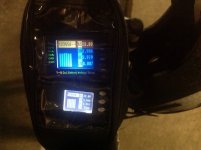
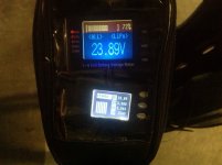
What do you guys think of the BVM-8S Cell-Log copy?
I will have to leave it going for a bit and see how it drains.

I ordered one off ebay for like $14 delivered and so far I think it craps all over the original Cell-log.
It comes with a external larger optional speaker for a louder warning beep and red LED.
Also it has a fairly significant larger screen so you can see the numbers more easy, you notice it once you have them side by side, also has a very nice total voltage/% view mode as well.

2012-12-22T01-58-46_0_Shrink.jpg

2012-12-22T01-58-46_1Shrink.jpg
 
TheBeastie said:
What do you guys think of the BVM-8S Cell-Log copy?
I will have to leave it going for a bit and see how it drains.

I ordered one off ebay for like $14 delivered and so far I think it craps all over the original Cell-log.
It comes with a external larger optional speaker for a louder warning beep and red LED.
Also it has a fairly significant larger screen so you can see the numbers more easy, you notice it once you have them side by side, also has a very nice total voltage/% view mode as well.

The biggest problem with the cell-logs is their diminutive display, especially since my eyesight isn't getting any younger. For the original target market, the RC guys, this is fine. So the BVM clone with it's slightly larger and more legible display will be a boon to us. So much so I just bought one.

Looking at the manual, it says it consumes 24mA when powered up. Which is quite significant.

As a design exercise, I'm going to see if I can't combine what Heath has created here, with some of the ideas from my own BMS design. Because I really like how my system completely shuts down automatically at the end of charge.

Would also be interested in seeing how the BVM unit goes mounted permanently to the handlebars. The cell-log is an epic fail at this due to lack of size.

Amanda
 
Heath,

I have another question.

Is there any reason why the HVC+ signal from the opto's doesn't connect directly to the gate of the Fet?
Seems to me there are 2 transistors and a number of resistors which are redundant.

Amanda
 
commanda said:
Heath,

I have another question.

Is there any reason why the HVC+ signal from the opto's doesn't connect directly to the gate of the Fet?
Seems to me there are 2 transistors and a number of resistors which are redundant.

Amanda

Now that I look at it, and I am easily confused since I have a problem with schematics on more than one page (personally I figure if you can't draw it on one page you can't fit it on one board, that's why we have 11x17 printers! :) ) so I may be missing something, but is CHARGER GND tightly connected to the ground symbol on your board? If not, then Q (fet) is going to have a hard time when it's off. The allowed gate to source range is +- 20V on most fets.

Maybe it would help if I knew what HVC "ground" connected to in the outside world.

By the way, I was looking at the alarm output of the CellLog8M today and I realized that the output transistor (Q9, a BC817 45V 500mA NPN) gate is driven through a 2K ohm resistor from pin 44 of the ATMega32A running at 3V. This gives it 1mA if you have a 1V drop opto. It seems to me we can open the CellLog up, replace the alarm transistor with a opto and not need to worry about the opto supply current since it would drive off the CellLog internal regulator and draw no more current than the transistor.
 
Otmar said:
. It seems to me we can open the CellLog up, replace the alarm transistor with a opto and not need to worry about the opto supply current since it would drive off the CellLog internal regulator and draw no more current than the transistor.

That should work great. I wish they would build them that way.
 
It would be nice but I can't blame them. Transistors are $.05 while Optos are $.50 and carry less current, gross that up and it adds $1.50 to retail.
OTOH, it sure would be nice if the PCB had the pads there for this mod, or they could even sell a +$2 "isolated alarm" model and drop the beeper.
Still, I'm just glad that the parts #s are not sanded off and it is easy to reverse engineer and play with it.
 
Sorry I have been a bit slow to reply on this, I've just taken on (another) new project on the house. Sigh. Solar installation. I hate being on the roof at the best of times...

The schematic was drawn after I built it ~ so it may be a little confusing. The gate is driven from 12V dreived from the reg, so gate voltage is between 12 and 0V. 0V is referenced to the charger (what is powering the charge control section, not the battery).

The transistors prior to the mosfet are a hangover from a different design that used them as gate drivers when being driven by optos - they needed to be sensitive as there is a region when the mosfet ends up in a linear region and gets bloody hot. I meant to revise the board but never got around to it, I gave it some thought and went F-it and built it anyway.
 
Found a bug.

Those KOTO reeds have a bad tenancy to stick in the closed position, so I need to find something that's more reliable. Shit.

Put it on the bike, and find this. Grrr....
 
OK - an update. I found some low-profile relays on fleabay (DPDT 5V) and dead-bugged them onto the PCB. Works fine now, should have specced them in the first place (sigh).

Now working as expected, and I added a pushbutton next to the displays hooked up from the top of pack 1 (ie. 22V) to the positive supply input where the charger would go. It has a diode so that if you are charging with 48V and press the button bad things don't happen (ie. you don't feed 48V into one pack (eeeeek!)). Means you can just press the button to get the pack SOC.

When you disable all of the splash screens, beepers, power management, info screens these things boot and display in under a second - nice!

Some Pics....

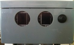
Cellog_Window.JPG

The lid closes nicely without interference, and all the wires fit - bonus :mrgreen:

 
.
 
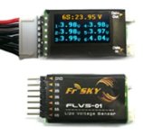
I found another cell-log like device, its called the Frsky voltage monitor, Model: FLVS-01
http://www.ebay.com/itm/281027511269
Claims it has a OLED display which I guess if true would mean less battery usage.
Also claims you can connect two together so you can see the total of both packs of 12s pack.
Any one used these before?
image.jpg

*Edit* to see voltages on two packs looks like you got to get one of these the frsky FLD http://pages.ebay.com/link/?nav=item.view&id=130685400925&globalID=EBAY-US
 
heathyoung said:
When you disable all of the splash screens, beepers, power management, info screens these things boot and display in under a second - nice!

How do you do that?

The FrSKY thing looks interesting. Somebody needs to get one for testing.
 
Its in the configuration menu somewhere - I'll have to see where for you, but yeah, when you kill off all the extra crap they are very fast to boot.
 
Back
Top