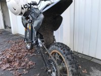
Chinese Pit Bike Conversion | Nucular 12F | LMX-Motor 60mm | 18s 16Ah LiPo

A fixed tensioner attached to the front of the swingarm which moves down onto the return chain path when the suspension compresses would be more elegant. Sprung tensioners need to be extremely robust to be effective.

The other option is lowering the motor to have correct chain tension at static sage.
 
@MorbidlyObeseKoala (what a name :lol: )
Are you nervous those aluminum channels will bend under the stress from your weight during impacts?
Yes I am nervous. Time will tell how well they hold up. But they seem pretty rigid for now. Unfortunately after a test drive yesterday I realised that this just isn't the perfect solution. Using a tube as foot pegs means you have a very small contact area which feels not very stable when you stand up. Need to change this to a real footpeg but for now it's better than before with the ability to fold back.

Aren't foot pegs usually mounted to those 2 holes in the lower part of the frame on pit bikes?
Could be. But as I wrote I didn`t found a set to screw on to the frame with an including tilt mechanism.

@SlowCo
Wouldn't a spring mounted like this be stronger and better (moving up with the swing arm)?
Thats what I did after some testing :roll:

@Grantmac
A fixed tensioner attached to the front of the swingarm which moves down onto the return chain path when the suspension compresses would be more elegant. Sprung tensioners need to be extremely robust to be effective.

The other option is lowering the motor to have correct chain tension at static sage.
I don't know if I understand your recommendation right. Could you draw me a sketch?

Lowering the motor is not possible due to width of it. I realised way to late that there is a reason why sprockets are not in line with the swing arm on motorcycles when they aren't loaded. Now I have to live with the problem of a chain that gets looser instead of more fixed when compressing the rear shock.


Spring tension part two and rear mud guard

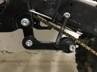
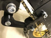
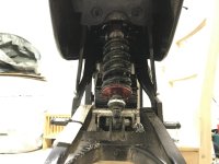
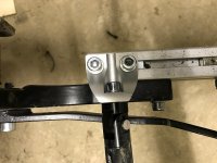
After trying around with different springs I came to the conclusion that it wouldn't work like I wanted it to work. Pushing the chain up with a leg spring needs a lot of force regarding the length of the lever. So I went for plan B that I already mentioned in my last post and SlowCo suggested.
I printed a new lever and and used one of the holes that already existed in the swing arm for the original chain guard.
K1600_IMG_7409.JPG
K1600_IMG_7410.JPG

On my test drive I changed the position of the upper screw that holds the spring to the top hole because the tension wasn't enough. This works really well. Will see how it will be effectedby dirt etc.

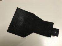
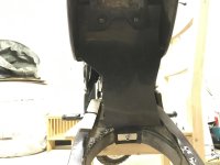
I also made a new mud guard for the rear. The old one was just temporarely and very fragile. Sadly I disposed the wide street tire the pit bike came with, it would have been a great mud guard...
I got myself a sheet of ~ 1mm thick abrasion restiant plastic and started to cut out the rough shape. After some test fitting and cutting it came out like this. Should do the job!

K1600_IMG_7412.JPG
K1600_IMG_7411.JPG
K1600_IMG_7413.JPG
 
If you got some longer bolts that attach the frame to the battery case, you should be able to get some chinese pit bike foot pegs from ebay or amazon. May have to be a little creative on the mount to the frame but they would be way grippier especially when it gets muddy or wet.

For instance:
https://www.ebay.com/itm/BLACK-FOOT-PEGS-YAMAHA-PW-50-80-TW200-PW50-PW80-50-PIT-DIRT-BIKE-M-FP02/360232669042?hash=item53df8a4f72:g:EVsAAOSwX61ZB37-
 
If you got some longer bolts that attach the frame to the battery case, you should be able to get some chinese pit bike foot pegs from ebay or amazon. May have to be a little creative on the mount to the frame but they would be way grippier especially when it gets muddy or wet.

You are right I defintely need to install "real" footpegs!
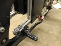
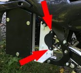
Mounting them directly to the frame is hard as the rear brake lever sits very close to the frame as you can see in the pictures. That's why I chose to mount them onto the aluminium profile.

K1600_IMG_7667.JPG
K1600_IMG_7671.JPG

For the future my plan is to get the rear brake to the left side of the handlebars. I'm quite used to a footbrake but as this bike is way smaller than my street bike you can't rest your foot on the peg and brake at the same time. When you want to brake the foot needs to hover over the brake.
Another (very :lol: ) important reason to do so is wheely control. At the moment only Powerwheelies (before tipping point) are possible as you can't reach the brake when the front lifts up.
Maybe I'm switching to a 200mm mountainbike break that I have laying around. Should work if I don't overstress it.


Small update: threaded bushings for the LMX-motor

A very uninteresting thing but I thought why leave it out on my build process.

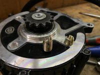
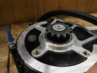
A while ago I 3D-printed a sprocket cover for the motor. It had two steel sleeves in it so that I could tighten up the two M6 bolts that assist the two main mounting bolts. But from the permanent screwing and unscrewing the soft aluminium of the motor gave up and both threads went useless after some time.

IMG_6783.jpg

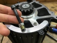
So I replaced them with threaded steel bushings. The existing hole was only 10mm in depth so I used a special thread cutter to get as much threads as possible.

View attachment 8
View attachment 7
View attachment 6
K1600_IMG_7593.JPG

The bushings were way too long and had to be cut down. With the help of a screw and a looknut the mounting was very simple.

K1600_IMG_7595.JPG

Glued in place with screw lock. The bushings are flush with the mounting surface.

K1600_IMG_7596.JPG
 
Nice mod :thumb: Contact us if you need spare parts, we have stock of old motors front covers and some other parts we can send you for the price of shipping

Adam
 
Nice mod :thumb: Contact us if you need spare parts, we have stock of old motors front covers and some other parts we can send you for the price of shipping

Thank you for the offer, I appreciate your help!
BTW what kind of rear chain guard do you use on the 161? All the ones I find online would need a rework because the width is to high for the narrow 219 chain... One solution would be to mill the middlepart down from 24mm to 16mm or something.


Watertight plugs, experimental rear chain guard and new sprocket cover

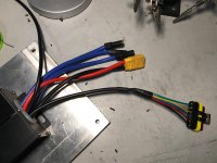
Another thing on my to do list, was to exchange the hall and temperatur connector from motor and controller. Initially I used two standard servo plugs to get it to work as they are small and I had them lying around. Now that my plan is to make the bike more and more resistant to water I changed them to watertight 6 pole connectors.

Before:
View attachment 15

After:
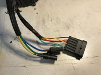
K1600_IMG_7673.JPG
K1600_IMG_7674.JPG

I also decided to cut off the plastic XT150 covers from the phase wires as they already came loose and weren't watertight anyway. To secure the contact I plugged the bare connectors together and heat shrinked it.


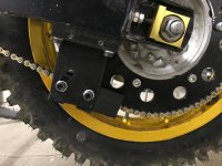
As the controller and motor were already out of the frame I disassembled all the plastic covers and turned the bike upside down to mount my experimental rear chain guard.
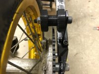
As this project started I used a small 63 teeth chainring on the rear and could therefore use the original rear chain guard the bike came with. But as I went bigger with the gearing I couldn't use the guard anymore so I sawed off the welded holding brackets.
But this resulted in the problem that the chain wasn't aligned anymore before hitting the chain ring and therefore jumped off sometimes. Especially when doing a 180 degree turn with one foot on the ground.
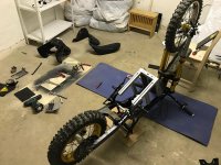
K1600_IMG_7677.JPG

For testing I 3D-printed all the parts.

View attachment 11

Test fit looks good. Real life test still on the to do list.
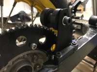
K1600_IMG_7679.JPG
K1600_IMG_7680.JPG

As I already had it upside down I also made a aluminium cover for the bottom side of the battery housing.

View attachment 8
View attachment 7

Then the reassembling.

View attachment 2

Cable management looks very clean now.

View attachment 1

Chainline from the side
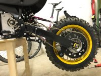
K1600_IMG_7690.JPG


I also made a new sprocket cover since the old one broke from a slapping chain.
As mentioned in my last post I use drilled out M6 nuts as bushings. So I can really tighten up the two M6 bolts without worrying about the plastic. The bushings are pressfited and also glued.

View attachment 5
View attachment 4
View attachment 3
 
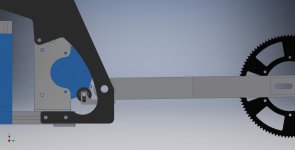
I'm not good at expressing myself with pictures so I will try to explain the tensioner I propose better.

It would sit between the swingarm pivot and the motor sprocket and be mounted on the swingarm so that as the suspension is compressed it comes into contact with the lower chain to take up the slack.

I think I got it now. You mean something like this right?


K1600_loaded.JPG

It would look way better than it is now with the spring! Much more hidden and less prone to error. But I'm a bit concerned about the amount of engaged teeth of the front sprocket. I will defintily note it to test and try out in the future!


Chain guard testing

As you can see my coworker hadn't the same positive attitude about my pulley-chain-guard-experiment:
K1600_IMG_7711.JPG

And he was right: the chain still fell off in an extreme situation (180 degree foot down turn) and I had to do the walk off shame. I don't know what happened exactly but I stopped the experiment with the pulley and deciced to make a more common chain guard.
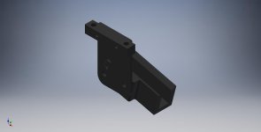
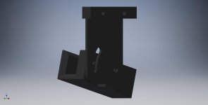
I designed this thing which kind of looks like a normal chain guard. It also features an adjustable angle to minimize wear on the soft 3D-prints and also minimize the noise while driving "normally" (only me as weight and no jumps etc.).
The idea is that the chain don't touch the lower part of the guard and is only guided by the sides if needed.

K1600_Chainguide_1.JPG
K1600_Chainguide_2.JPG

After printing and mounting it looked like this:

K1600_IMG_7712.JPG
View attachment 6

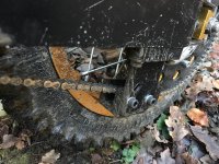
I then went outside to try it in the mud and I was quite surprised that it hold up all my tests. My all time anxiety was the chain jumping off since the start of this project is now vanished. :lol:
And lesson learned: a chain guard is a must have if the distance between the axis varies!

View attachment 5
K1600_IMG_7767.JPG

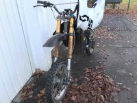
Now the bike looks like it should. Better than any paint could do it 8)

K1600_IMG_7769.JPG
K1600_IMG_7770.JPG
 
Yes you have it precisely! I hadn't thought of tooth engagement but I don't think it would be very significant. I can envision a version which uses a simple linkage to increase engagement but putting that into words is more challenging.

Having as much slack as possible without tossing chains is definitely important for efficiency and wear however.
 
That's a really nice project, I have a question.
Did you have to pay extra taxes when importing the Nucular 12F controller?
Thanks. Regards.
 
Did you have to pay extra taxes when importing the Nucular 12F controller?

No, both of the nucular controllers 12F and 24F came without any extra payment whatsoever to my adress in Germany.
 
Back
Top