Commuter Booster - <1kg Friction Drive

What throttle are you planning on using?

I am about to get a Recumpence-throttle in the mail. I have parts for several different affordable throttle options, but I want to start with a proven throttle system so I'll know that any problems that arise are from somewhere else.

Based on the experiences of Kepler and others, I have started my RC-work with the 63mm motors. edit: nothing wrong with the 50mm motors, several are getting good results and also identifying the proper combinations and operating parameters to make them a useful choice. I just wanted to have more mass as a safety margin while I am stumbling towards my end goals.

If the entire drive gets sorted out, I will begin swapping in equipment options one at a time to see how each affects the overall performance. I want to identify weak links, and then find the dividing line, so I can record some data with a reasonable amount of accuracy. Some builders want to run right on the ragged edge, and others want to know where the edge is, so they can stay a few feet back (even if it costs a few dollars more)...
 
adrian_sm said:
adrian_sm said:
Kepler said:
I agonised with the weight thing and the larger diameter but for the sake of an extra 400 grams, just couldn't go past the 63-74. I have bought 20 of them now and never had a failure yet.

Are you running these on 6s? Have you taken any steps to stop overheating?

Sorry just re-read your earlier post.

63-74 on 5s, resistor mod to currie throttle, limits things to ~1500W.

So If I limit my throttle somehow to give similar 1500 watt peaks, I should be getting closer to a robust system.

I just realised another solution, I have a Cycle Analyst - Stand Alone. I could use this to take control of the throttle. This will make tuning things a lot easier.
Will have to look in to how hard that is going to be.... Or get my mate full-throttle to write up a bit of code for me, and modify the watt meter to do the same thing, but something tells me de-bugging two systems at once is not a good idea for some reason.

5S reduces your overall watts due to the motor not having the same voltage to work with. Also lower top speed means lower watts. Then limiting the throttle to around 90% drops it a bit further. I have found the ESC can run fine at 80% and above without overheating problems. This is within their design peramiters of an RC controller and basically where a model aircraft tends to spend most of its time.
 
On a further note. I think the motor you used would have survived if you had run it on 5S and limited the throttle to 80 or 90%. If you can rebuild on good motor out of what you have, it would be worth trying again with your current design.
 
umejopa said:
Good work to make throttel inteface of a watt meter :D What uP is in it ? Have take my apart now :D
Can I borrow some code from you full-throttle ??

//Jonas
Cheers Jonas,
The uC is ATtiny x61 series, not sure if its a 2k, 4k or 8k option - the markings are rubbed off and the chip is read protected. I simply took the uC off and whacked a blank one on.
As Adrian mentioned, the schematic is out there, however there are a few discrepancies.
There's nothing special in the code, just some ADC, PWM and LCD routines.

adrian_sm said:
I just realised another solution, I have a Cycle Analyst - Stand Alone. I could use this to take control of the throttle. This will make tuning things a lot easier.
Will have to look in to how hard that is going to be.... Or get my mate full-throttle to write up a bit of code for me, and modify the watt meter to do the same thing, but something tells me de-bugging two systems at once is not a good idea for some reason.
Go with CA for now (its very simple), I've got a bigger fish to fry at the moment, but would be very interested in making the watt-meter work for the friction drive.

Keep up the good work!
 
Kepler said:
5S reduces your overall watts due to the motor not having the same voltage to work with. Also lower top speed means lower watts. Then limiting the throttle to around 90% drops it a bit further. I have found the ESC can run fine at 80% and above without overheating problems. This is within their design peramiters of an RC controller and basically where a model aircraft tends to spend most of its time.

Great info. Thank you so much. That has probably saved me weeks of effort, and various burned up motors and controllers.

Kepler said:
On a further note. I think the motor you used would have survived if you had run it on 5S and limited the throttle to 80 or 90%. If you can rebuild on good motor out of what you have, it would be worth trying again with your current design.

Well the motor/drive rebuild is done. All ready to go, but just need to order some 5S LiPo.

But the temptation will be to just limit my throttle, on 6s, in the mean time. Of course this will just let me find the limits of the controller instaed, by burning that up. :lol:

I should really get a more robust design working first.
5s, 63-74, plus drive learnings from this version. Let's hope I can get some time on the weekend to make it happen.
 
Thanks. That is very generous of you John. If I get impatient I might just take you up on that offer.
 
Update:

1) 5s LiPo
- Order some 5s LiPo & a cheap charger that I can leave at work, so I don't have to carry one around.

2) No load test
- 64 kph on 6s charged to 4.1/cell :shock:

3) Cycle Analyst
- Took it off the giant, and got it on the road bike/test mule for the friciton drive.
- Now trying to work out how to get it to over-ride the throttle and need a bit of help.

The cycle analyst manual says do this:
CA Throttle Overide.PNG

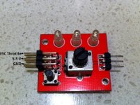
I am using a cheap turnigy servo tester, and am not positive of how to wire up the CA to the servo tester.

Here are some photos of the servo tester, and the relevant inputs, outputs, and pot pins.
View attachment 1
IMG_1303.JPG

At the moment I can't see any resistor between the pot output and the chip.

So I am thinking of desoldering that leg (Pot Signal), putting a resistor in line between pot output and the solder point.
Then bringing in my CA throttle overide wire, with diode in line, and soldering to the same point.

Does this look right?

Also the ESC BEC output that is feeding the servo tester is 5.5V.
The CA can only go up to a max of 5.0V. So I think this will mean I always am pulling down the max throttle to 5.0V, or ~90%.
Since Kepler was advising this anyway, it might be a good thing anyway. But it means I will never be going full throttle if I implement the CA throttle overide circuit.

- Adrian
 
So the pot is just a variable resistor, ~9.2kOhm -> ~20 Ohm.

Adjusting the pot to 5.0V output, gives a resistance measurement of ~950 Ohm between the 5.5V and output.

So if I put a 1kOhm resistor in line with the output, this should limit the throttle to ~90%, matching the servo testers max throttle to what the CA can control, and limit current so the CA can safely sink the voltage to acheive throttle override.

Do I need to do this to protect the CA, or can I just wire the CA throttle override line, with diode, straight to the output of the pot. The ebikes.ca CA page (Throttle Over-Ride Details section) says they have a 1kOhm resistor in line on the CA PCB to protect the op-amp, so this should all ready limit the current to something safe so I don't blow up the CA.

I am tempted to just put put a diode protect link straight to the pot output leg of the servo tester. But being an electronics idiot, wouldn't mind someone giving me a reality check first.

Cheers,
Adrian
 
Adrian,

You will need to protect the pot from the worst case (when the pot is close to full) as there will be very small resistance between the power supply and wiper. When CA pulls the wiper to ground via the diode all of the current will go through that resistance.
Example1: 5k pot, 80%, resistance 1k - current ~ 4.3mA
Example2: 5k pot, 99%, resistance 50ohm -current ~ 86mA
If you go too far the pot will burn..

Either place a 1k inline on the wiper or the power to the pot.

Edit: looking at the pics of the servo tester it looks like there's a resistor to the 5.5V pin on the pot
 
Will the 1 kOhm in the CA do that job?
 
G'day Adrian, if I understand what you are doing, adding a resistor to the output of the pot will not reduce the voltage. You need to add resistance to the 5v5 input side of the pot like this. By using a 5K trimpot you can set the voltage precisely over a range of approx 4V to 5.5V.
Trimpot.jpg
 
Thanks guys.

I am trying to do two things:

1) be able to hook up the CA to use it's throttle over-ride functions. While not blowing anything up. ie. CA, servo tester pot, etc.

2) have it still able to go to 100% throttle.

I don't really care about #2, if max is still 90%, mainly just #1.

-Adrian
 
Tried connecting the CA via a diode to the pot, with no additional resistors.
Set the CA speed limit to 30kph.

Plugged it all together, started it up, no smoke.
Accelerated up to 30kph, and a bit beyond, less than half throttle. The CAthen took over and started reducing the throttle to maintain 30 kph. :D

Then accelerated a bit more, and the speed started to increase again. :(

All the way up to full throttle no load speed of 67 kph.

So it looks like the CA can't sink enough current to pull the thottle signal down.

Quote from the ebikes.ca site:
ebikes.ca said:
The over-ride output is an analog voltage that can range from 5V down to 0V. When it detects that a limit is exceeded, the voltage begins to ramp down from its resting point (set by ItermMax), until power to the motor is reduced and the limit (speed, current, or voltage) is no longer exceeded.

The actual output is derived from an op-amp on the circuit board, and it is capable of both sinking and sourcing current. In the original Cycle Analyst boards (identified by a lack of label on the PCB) this output was wired directly from the op-amp, so it was quite stiff, but also made the board vulnerable to damage if the Throttle Over-Ride was accidentally wired incorrectly to a voltage source. In PCB revision 7 (labelled DB2 Rev7b), the output line was modified to include a 1k resistor (R6) to protect the silicone. This however means that the Over-Ride line can only source or sink small currents, and if more than a mA needs to be drawn from the output, then resistor R6 should either be reduced in value to a couple hundred ohms, or possibly shorted out entirely.

Does this mean I should crack open the CA, and drop the value of R6?

- Adrian
 
Update:

I had trouble with the original manufacture of the hole in the bearing support side pivot arm/plate.
I originally attempted to used a hole saw to make the bearing hole, thinking if it is a bit big I'll just glue it in. But it was way too big to just glue up.

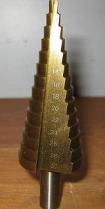
So I bought a step drill of ebay, 48hours later I made a new side plate and the fit is much better.
The good thing about this is that I thought this hole might need to be milled to be good enough, but the step drill worked a treat.
Now all the parts can definetely be made with a drill, and hacksaw or angle grinder. Which means most people can make this at home, with minimal tools. :D

Since the plate is 10mm thick, and the step drill has a step size of ~4mm, I needed to drill from both sides, and chamfer the enter on each side slightly too. But there is still more than enough support for the bearing, so I am a happy man.

Here is a pic, before I had got rid of the little ridge in the centre of the hole.
Actually I have left some of it, and will press the bearing in to place and use the ridge to take up some of the clearance.


- Adrian
 
$31.50 delivered, from these guys.

First time I have dealt with them. Good communication, quick delivery. Time will tell on the quality.
 
Nah. 4 - 30 mm.

I needed 22mm for the bearing.

4-30mm Step Drill.PNG
 
adrian_sm said:
Will the 1 kOhm in the CA do that job?
It will protect from shorts, you're right. However, not having a series res on the servo will make the effect of CA very weak (as you've experienced)
adrian_sm said:
Does this mean I should crack open the CA, and drop the value of R6?
Ideally you'd want it shorted and a 1k - 3k3 on the servo
 
Update:

1) Torsion Spring
I have increased the spring stiffness. The last one was too light to take the torque of the motor weight.
This new one is better, still not right, and I might be able to make it adjustable with a screw rather than the current bend the spring to the right shape method.
I now have the drive tuned such that the motor just touchs the tyre. I might back it off a bit later, but it works for now.

Note: This was the method Kepler appears to use when setting up one of his eboostdrives.
- When the tyre spin forward it just drags on the motor but not enough to spin it.
- When you spin the tyre backwards the motor actually engages and spins.

3) My new back tyre is not round.
:x

3) No Load Power Test
Now that I have the Cycle Analyst on the friction drive bike, I thought it was time to get some data.
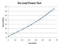
So here is the no load power the drive requires just to spin the wheel.

Commuter Booster - No Load Power (2010-11-09).PNG

Note 1: The no load power consumption of the motor alone at full throttle is ~52W.
So only about 12W for the light engagement friction drive loses, and to keep the wheel spinning.

Note 2: There is no load on the tyre, so the drive is only lightly engaging with the tyre.
When fully engaged the power required is a lot more. ie. 160W total at 66kph. :shock:
So about 100W more than minimal engagement. That is like ten times the losses. Yikes.
I think I might need to spend some time optimising the engagement.

Note 3: The ambient temperature was 22 deg-C, and the motor temperature stablise to about 49 deg-C after 10mins a full thottle.
This means a 27 deg-C temperature rise for about 50-60W of waste heat.
Will be interesting to compare this figure to other motors, as the motors ability to dispense heat is key to survival for light drives like this.

That's it for now.

- Adrian
 
Thats good data Adrian. The drive setup against the tire is how I setup my drive as it does need the lightest contact to pickup cleanly every time. Still has no impact in relation to drag on the bike with this setup though.

As you have proved, having the contact either off or full pressure contact is not the best for efficiency. I came to the same conclusion during my development and was the reason why I designed a damper arrangment. Progressive contact pressure is the way to go. I look forward to seeing what arrangment you come up with. Finding the right damper material is the key. You need to find a material that gives the correct amount of compression but also has good rebound properties. Rubber sheet from Clark rubber works OK but its rebound property isnt very good. I am still looking for the perfect material for this. I am thinking silicone rubber would work well but its hard to find in sheets. Spinningmagnets suggested the silicone rubber used in making the soles of shoes. There was also a suggeston to mold your own using a silicone based modeling material.
 
Kepler said:
Thats good data Adrian. The drive setup against the tire is how I setup my drive as it does need the lightest contact to pickup cleanly every time. Still has no impact in relation to drag on the bike with this setup though.

As you have proved, having the contact either off or full pressure contact is not the best for efficiency. I came to the same conclusion during my development and was the reason why I designed a damper arrangment. Progressive contact pressure is the way to go. I look forward to seeing what arrangment you come up with.

Why can't this be done purely by the geometry? I have it in my head that the angle between the pivot point, the contact patch, and the wheel axle sets the ratio of contact pressure to motor torque. So by adjusting dead-stops, and pivot point locations, you should be able to set the correct contact pressure ratio to ensure you don't get slip.

Your dampener material I believe is essentially just reducing the contact pressure for a given torque. If the drive started with a bigger angle (mentioned above) to start with, while still maintain your just touching scenario, you could reduce the force required by the dampener. But the system might become more sensitive the tyre pressure, or geometry imperfections such as out of round tyres. I know you mentioned something about the drive bouncing off the tyre, maybe that is another reason for your geometry & dampener set-up.

I feel like I am really missing something here. I need to play with it more to understand.

Thanks again for helping out.

- Adrian
 
You can do it just with geometry if you are happy to accept a fixed loss due to the pressure exerted on the tire when the drive is activated. However, you can get away with less contact pressure under lighter loads and hence less loss. It makes sense to me to try and capitalize on this using progressive contact pressure strategies.
 
When I say via geometry, I don't mean locking the drive to a position, and hence fixed losses.
I am still talking about a free to pivot progressive contact pressure just like your design, with the motor torque dicatating the contact pressure. I just want to limit the maximum engagement via a deadstop so I can stop too much contact pressure. I think you acheive the same thing but by using a soft-stop, ie. your foam dampener. This applies more and more reaction force as the drive engages, until a balance is found. I was think of a more defined stop to limit excess contact pressure, and hence losses.

Here is a pic of where my motor sits.
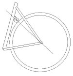
Friction Drive Geometry - pic1.PNG

Here is a close up of the motor to tyre contact.

The motor torque grabs the tyre, resulting in the driving force in green (F1).
The geometry (specifically the angle shown with a double headed black arrow) sets what the resulting contact force with the tyre will be (F2)
If the coefficient of friction is high enough, then F3 = F2 x coefficient of friction > F1. And the drive will bite, and not slip.
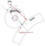
Friction Drive Geometry - pic2.PNG

If the pivot point moved to the right, then you would get a lower contact force (F2)for an identiacal driving force F1, and more likely to slip, but less losses.
If the pivot point moved to the left, then you would get a higher contact force (F2) for an identiacal driving force F1, and less likely to slip, but more losses due to deflection of the tyre.


So for me the coefficient of friction dicates the maximum angle necessary to apply the contact pressure required to ensure the drive doesn't slip.
For a perfectly stiff tyre and motor, there would be no more angular travel after initial engagement.
Softer tyres will need more travel angle between pick-up point and fully engaged.
Stiffer tyres will require less travel angle, as the contact force will increase more rapidly.
Higher torque means higher contact pressure required, which means bigger travel angle.

If you get the geometry right, then F3 [EDIT - Ooops had written F1 before by mistake] is only slightly bigger than F1 to ensure engagement, and miminal losses. But in reality you will have a decent safety margin, so out-of round tyres, or tyre deflaion doesn't mean you start burning holes in your tyres.

Does that make it any clearer ? Or am I just confusing myself, and everyone.

- Adrian
 
Back
Top