Contactor circuit blowing fuses

cboy

100 W
Joined
Sep 18, 2017
Messages
179
Location
CA Central Valley
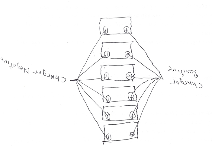
I have a Kelly ZJW 72V/400 amp contactor which powers dual Kelly KLS 7230S controllers and dual QS Motors hub wheels. A few days ago (as some of you may have seen in my post on that issue) I couldn't get the batteries (6 lead acid deep cycle) to charge above 74 volts. Turned out to have been a blown fuse in the charger resulting from the charger contacts be wired in reverse. Once that wiring was corrected, the batteries charged up without a problem.

This morning, however, when I went to turn the bike on there was no power to the ignition circuit. That was quickly traced to a blown fuse in that circuit. Using my Power Probe (a dead short detector) I quickly traced the cause of the blown fuse to a "short" in the wire leading to the contactor relay. But then things started to get confusing.

The positive side of the relay is fed off the ignition switch and a 2 amp fuse. The negative side of the relay goes to a grounding pin on each of my controllers. My Power Probe indicates those controller ground pins are ALWAYS a dead short to ground...whether the key switch is on or off. I'm not sure if this should be the case but that is what the testing shows.

If I disconnect the ground wire between the relay and the controllers, my ground short in the relay wire disappears.

If, in fact, the controller ground pins are always grounded to the battery negative terminal, what limits the amount of amperage through the wiring? Is it the "draw" of the relay coil or is there some sort of limiter within the controller that prevents full battery amperage from going to ground? If I am diagnosing the problem correctly it seems the relay wire is drawing full amperage out of the battery pack and sending it directly to ground...so a major load of juice. Could that indicate a malfunction in the relay coil that then allows full amperage to go to ground?

And then there is the issue of "why now?" The system was functioning well. Then I blew the fuse on my smart charger because the leads were installed backwards. But even after that blown fuse, the system was functioning properly. I could turn the key switch on and off and all the systems responded...the controllers would come on and the Cycle Analyst would come on and give a current battery reading. This issue (the blown fuse in the contactor relay circuit only arose AFTER I rewired the smart charger correctly and AFTER it had fully charged the batteries. Now nothing comes on since the controllers, the Cycle Analyst and the key switch are all on the same fuse as the contactor relay.

Here are the results of some of the diagnostics I have done thus far.

* The contactor relay wire will show a short to ground with the key on
or the key off. I have the contactor relay grounded to pin 6 of
controller A and to pin 6 of controller B. The pin itself, (pin 6 on
both controllers) always shows it is shorted to ground whether the key
is on or off. This may be normal...don't know.
* With the contactor relay diode in place and all other wires
disconnected , I get a multimeter continuity reading of 286 Ohms when the
probes are on the incoming tab of the relay and the ground side tab of
the relay. With the probes in the same positions, the multimeter shows
a diode reading of .147 volts.
* I have tested the diode when removed from the relay. I get a reading
of 31.4 k Ohm in resistance mode and .471 Volts in diode testing mode. I also tested an identical "new" diode and got almost the exact same readings. Do I think the diode is good.
* With the contactor relay diode removed and a jumper wire installed in
its place, I get a resistence reading of 7 Ohms. Diode reading on the multimeter is
obviously zero.
* With the ground wires connected from the relay to the controllers, my
Power Probe (ground short detector) indicates a short to ground when I
touch the incoming (hot in) tab of the relay. If I disconnect the
ground wires to the controllers, no short is detected.
* I tried testing the amperage across the fuse holder while the
contactor circuit was connected, but with just the slightest touch of
the probe I got a major spark which actually melted the tip of the
probe. So this appears to be a major league short to ground.
 
Continuing research: The ZJW relay coil is supposed to draw 0.1 amp or less. So clearly there is something amiss in the coil since mine is drawing way way way more than that...so much amperage you can't put a multimeter in the line without melting the probe tips. I've got a message into Kelly and they are usually excellent in getting back on troubleshooting. My guess is...new contactor. But I also want to try to determine what went wrong so it doesn't happen again.
 
cboy said:
The positive side of the relay is fed off the ignition switch and a 2 amp fuse. The negative side of the relay goes to a grounding pin on each of my controllers. My Power Probe indicates those controller ground pins are ALWAYS a dead short to ground...whether the key switch is on or off. I'm not sure if this should be the case but that is what the testing shows.

AFAIK, there should only be a ground there when the controller's KSI (key switch input) is turned on. There's logic in the controller to ground that line at that time, to turn the contactor on.

If they're always grounded, something may have failed inside teh controllers.


If I disconnect the ground wire between the relay and the controllers, my ground short in the relay wire disappears.
Does the ground short still exist at both of the controller pin(s) for the relay ground, when the relay wire is disconnected?


If, in fact, the controller ground pins are always grounded to the battery negative terminal, what limits the amount of amperage through the wiring? Is it the "draw" of the relay coil or is there some sort of limiter within the controller that prevents full battery amperage from going to ground?
The coil itself should limit the current, by it's internal resistance.

To test the coil itself, you can disconnect at least one end of it from the system and the diode, then measure it's resistance with the multimeter across coil positive and coil ground. You should get enough ohms to limit it's current at it's rated voltage to the amp draw the specs list. (I didn't see this in your test list). Most likely it's going to read the 286 ohms it did with the diode in place, since the diode readings sound normal.

At 81v (about fully charged for 6 12v SLA in series), I get about 0.28A for 286ohm coil resistance.

If you do get the right resistance, you can test the contactor by putting the rated voltage across teh coil, and it should click the contacts closed or open as voltage is applied to or removed from the coil. Put a household 100w incandescent bulb in series with the voltage in place of a fuse, and you can see if it's drawing too much current if the bulb lights up or gets warm. :)


Because of the readings you got, the below is unlikely, but just in case:

I dont' know what the coil rating for your contactor is, but if the relay coil (ignore the contact ratings) is rated for a high voltage, like your traction battery voltage, it'll be a much higher resistance than if it is rated for a low voltage, like 12v lighting system voltage.

If a coil meant for 12v is run off say, 72v traction battery, that's at least six times the voltage, and six times the current thru it, and therefore much more heat in it by ohm's law (and it would probably smell hot). If its' well designed it might survive this for a while, but eventually something will fail. If the insulation on the coil fails, windings short to each other and the resistance goes down (and current goes up). If it shorts to a low enough resistance, it'd appear to be a direct wire from battery to ground, and poof goes the fuse.


And then there is the issue of "why now?" The system was functioning well.
IIRC, it was functioning well at the partly-discharged main pack voltage, of around 12v per battery, so around 72v total?


This issue (the blown fuse in the contactor relay circuit only arose AFTER I rewired the smart charger correctly and AFTER it had fully charged the batteries.
After fully charging them, they'd be around 13.6v or higher on each one, so 81v or more, right?

If the coil voltage is for a lower voltage like 12v, it might've survived the current at 72v, but not at 81v; could've been just enough to do it in.

It could be possible that something in one or both of the controllers failed at the higher voltage for unknown reasons, but that still shouldn't cause the coil ground to be a dead short to coil positive.


I have the contactor relay grounded to pin 6 of
controller A and to pin 6 of controller B.
Is it possible that Kelly doesnt' support having both contactors directly connected together on those pins? If they are using open-collector drivers on them, they should, but maybe they aren't.

If they don't, maybe one of the controllers took out the other one's driver when it's driver failed (shorted to ground)?


* With the contactor relay diode removed and a jumper wire installed in
its place, I get a resistence reading of 7 Ohms. Diode reading on the multimeter is
obviously zero.

Unless something has failed shorted (diode or coil), there should never be a short across the coil that way, so this particular test doesn't really mean anything, if testing the coil and diode separately and together revealed no short. :)

The diode should be wired across the relay coil pins, coil positive gets the striped end of the diode, and coil ground gets the other end. (in a schematic, the arrow would point toward the positive). The diode is only used to short out the inductive voltage spike off the relay coil when it turns off, so it doesn't blow up your controller or other things connected across it.


* I tried testing the amperage across the fuse holder while the
contactor circuit was connected, but with just the slightest touch of
the probe I got a major spark which actually melted the tip of the
probe.

Just an FYI: If you had the meter set to Amps and put it's probes across a voltage, rather than in series with a current, it could indeed give you quite a spark because the meter's shunt is essentially a dead short (so it has minimal interference with teh circuit being measured for current).

If you did have it in series with the (empty) fuseholder contacts for the test, and got the spark, then there is certainly a heck of a short downstream.
 
amberwolf said:
The diode should be wired across the relay coil pins, coil positive gets the striped end of the diode, and coil ground gets the other end. (in a schematic, the arrow would point toward the positive). The diode is only used to short out the inductive voltage spike off the relay coil when it turns off, so it doesn't blow up your controller or other things connected across it.

Well, that pretty much cuts to the chase. I had it wired the other way...striped end to negative. And I recall being very concerned about getting it right when I was putting it in. But clearly I didn't get it right. A very expensive rookie mistake. Looks like I've bricked two controllers and a contactor. The system must have been able to withstand my error until it got a really big jolt (or multiple jolts) from that coil when it was being turned off.

In spite of being highly depressed about my error, I do want to thank you, amberwolf, for spending a LOT of time going over my question and sharing your knowledge and insights. You may have brought bad news...but you are a very helpful guy. So I guess the next step is to either rob a bank or start a Go Fund Me to replace all these bricks.
 
cboy said:
I had it wired the other way...striped end to negative. And I recall being very concerned about getting it right when I was putting it in. But clearly I didn't get it right. A very expensive rookie mistake. Looks like I've bricked two controllers and a contactor. The system must have been able to withstand my error until it got a really big jolt (or multiple jolts) from that coil when it was being turned off.
It's possible, unfortunately--that's why the diode is there. :/ I learned about those diodes the hard way, when I started building various projects (not motor stuff) decades ago (feels weird to say that :oops: ), and blew relay drivers up a lot....

But it's possible that nothing is wrong except the diode is dead, and everything else still works...mostly.

FWIW, usually the striped end would go to negative, when using it to pass current like in a throttle or power supply, charger, etc. Just not in this case (and a few others). Wait till you learn about Zener diodes. :lol:


In spite of being highly depressed about my error, I do want to thank you, amberwolf, for spending a LOT of time going over my question and sharing your knowledge and insights. You may have brought bad news...but you are a very helpful guy.
I try.... :oops: Really just passing forward all the help I've gotten to get where I am now. :)

I've blown up enough stuff over the years to quite possibly fill the complete volume of a couple of rooms just with the dead components, not coutning anything else in the projects. :oops:

My favorite one on the SB Cruiser trike was to almost set the wiring on fire TWICE by working on it live without any fuses. The second time while I was thinking the whole time "I ought to stop and put a fuse in there", right up until the smoke started. :(


So I guess the next step is to either rob a bank or start a Go Fund Me to replace all these bricks.
If you're lucky, the Kellys aren't bricked. It's possible that Kelly will exchange or repair them if they are, for cheaper than new ones.

The most likely thing that would be killed by the diode issue is jsut the contactor driver circuit, and if so the rest of teh controller probably works. You'd just have to manually switch the contactor, instead of having the controllers do it for you. There's a few ways of that, but before going into it, you can just test the system by manually grounding the contactor coil (which is probably fine; see the test I suggested in the other post).

For a new diode (if it's needed), you can take a diode out of an old power supply (like say an old computer PSU), off the input side. SOme use a rectifier bridge, but some use individual diodes. Almost any of the black plastic diodes that are about 1/4" long and 1/8" thick, or bigger, will probably work.

Put the diode across the coil, line on the positive coil contact, other end on the negative.

With everything wired exactly like you had it when it worked, *except* the wire between the two controllers' contactor driver pins and the contactor coil negative (ground) pin will be left out.

Just in case something goes wrong, use that 100w incandescent house lamp hooked up with one wire to the system ground. The other wire youll use to ground the contactor coil's ground/negative pin, after turning on the keyswitch like normal.

When you ground the contactor coil's pin (the one that was left unconnected for this), the contactor should click, and the system should turn on. The bulb may light up too, if there's enough current thru it. ;)

If it won't click, then something else is wrong. Either there's not enough current to make the coil close the contactor, or the coil is damaged and not passing any current (can test that with the A function of your meter in series with it), or there's a connection problem somewhere in series with it between power and ground.

If it does click but nothing else turns on, then either something is disconnected, or the contactor is not making a complete closure, etc. The contactor can be bypassed to at least test the rest of the system if this is the case.

If it does click and everything appears to turn on, but the controllers don't operate the motors, or flash an error code (if they ahve LEDs for that), there could be something wrong with them.
 
amberwolf,

I'm going to follow up on the last post of yours (probably tomorrow) but just wanted to quickly report that I'm also in troubleshooting mode with Fany at Kelly Controllers. She had me direct wire the battery plus side to the rest of the system, totally bypassing the contactor. When I did this and switched on the key, the controllers both came on with green lights and I was able to put the trike up on blocks and spin both hub wheels with good throttle control. So it appears the controllers are not fried. I'm still trying to get straight about that "always on" ground circuit that the contactor relay feeds into but we are making some decent progress. She indicated the relay should show a resistance of about 380 ohms when tested without the diode in place. Mine is showing about 280 ohms. So that may be a concern. I will next try your "test" of the re-wired contactor relay circuit, with the lightbulb indicator...but it will have to wait until morning for me to get that rigged up. All in all...I'm getting less depressed by the minute.
 
See, good news already. :)

I'd guess that from the ground probe reading on the contactor output pins of the kellys that one or both of them has a stuck-on coil driver. It's probably just a transistor, but might be a chip. If the controllers aren't potted, they're probably easy to replace.

However, if that's problematic, and Kelly can't or won't do affordable repair/replacement, there are ways around it, by driving the contactor with the keyswitch itself (either via another relay, or using a multipole keyswitch, so one pole supplies positive voltage to the Kelly KSI pins, and the other pole supplies ground to the contactor).
 
Progress but now another issue.

amberwolf said:
Put the diode across the coil, line on the positive coil contact, other end on the negative.

With everything wired exactly like you had it when it worked, *except* the wire between the two controllers' contactor driver pins and the contactor coil negative (ground) pin will be left out.

Just in case something goes wrong, use that 100w incandescent house lamp hooked up with one wire to the system ground. The other wire youll use to ground the contactor coil's ground/negative pin, after turning on the keyswitch like normal.

I ran this test (but only had a 90W bulb on hand) running the ground directly to system ground rather than through the controllers. The conactor clicked on, the controllers came on with no error codes and the bulb did not light...or if it did it was too dim to see.

I then ran a prior test you suggested. I replaced the fuse with the 90W bulb putting it in series across the fuse holder. I attached the rest of the positive side of the relay normally (power from the key switch) and hooked the negative side through the ground pins on the controllers (as it had been set up previously). This also clicked the contactor and turned on the controllers without any error codes. However, the bulb did light up...although dim. It seems strange to me that I would get different reactions from the light bulb. Seems to me the resistance in the coil should be exactly the same either way. But I'm a little spooked about hooking this up through the controllers at this point. I'll run the tests again when my new contactor arrives. According to Fany the new contactor should have coil resistance in the 380 Ohm range while mine is in the 280 range.

While everything is much improved on the contactor/controller front, another major problem cropped up over night. My battery pack had depleted to just 55 volts. And this was with the Big Red Button turned off...thus isolating the battery pack from the rest of the system. I've now disconnected everything from the battery pack including the emergency shut off and I've put the charger on the pack. I'm not sure if it signifies anything but on the 10 amp setting the charger is only inputting about 1.5 amps (using a clamp meter around the positive contact). Is there a test I can run with the pack still wired up that would tell me if one or more cells have been damaged or where this voltage bleed is coming from? Getting at the pack to individually test batteries is going to be a real PITA.
 
cboy said:
I ran this test (but only had a 90W bulb on hand) running the ground directly to system ground rather than through the controllers. The conactor clicked on, the controllers came on with no error codes and the bulb did not light...or if it did it was too dim to see.
Just means that current thru the bulb was very low, which it should be. Assuming my math cells are not still asleep today, then with the coils measured resistance of 230ohms, there shouldn't be more than a third of an amp or less even at peak charged voltage. At the average of 72v, with just coil resistance, it's barely a quarter amp.

Even if all that power was across the bulb, it's less than 20w, so while it might make the bulb warm, it probably wouldn't light it up visibly in a lit room.

Actual bulb wattage doesn't matter, but 100w are a generally safe bet to use for troubleshooting. 40w can be used if it's all you have around (just will get hotter faster if you pull more current than it expects while testing).

I then ran a prior test you suggested. I replaced the fuse with the 90W bulb putting it in series across the fuse holder. I attached the rest of the positive side of the relay normally (power from the key switch) and hooked the negative side through the ground pins on the controllers (as it had been set up previously). This also clicked the contactor and turned on the controllers without any error codes. However, the bulb did light up...although dim. It seems strange to me that I would get different reactions from the light bulb. Seems to me the resistance in the coil should be exactly the same either way.

That *is* strange--if the wiring path is the same, you should get the same results, whether the bulb is in teh positive wiring or the negative.

Since you don't, you should go over your wiring very carefully, and see exactly where it is different than it should be.

The first test I would do is put the coil negative to system ground instead of controller contactor pins. This should be the exact equivalent of the first test, but iwth the bulb in place of the fuse.

If it is different results, then there is something about the cotnroller's contactor out that has "lower resistance" or "greater voltage potential" than the plain grounded circuit.

At that point, measure voltage between the controller's contactor out pins (which at this point aren't cnnected to anything external), and system ground.

There should be zero volts. But I am expecting you will see a negative voltage. I don't know how it could happen, unless your system ground actually goes to teh positive of one of the batteries instead of the negative, but that's the only explanation I can think of for a bulb that lights up in the fuseholder when using controller contactor pins for contactor coil ground, vs a bulb that does not light up in the fuseholder when using system ground for contactor coil ground. Since resistnace wouldn't change, the voltage would have to change, to cause more current to flow thru the circuit (which would be required to light up the bulb).


But I'm a little spooked about hooking this up through the controllers at this point. I'll run the tests again when my new contactor arrives. According to Fany the new contactor should have coil resistance in the 380 Ohm range while mine is in the 280 range.
That likely doesn't make any difference, except that with your contactor, max coil current could be as high as almost a third of an amp, while the new one would be max of about a fifth of an amp. Unless the controller contactor pin has a limitation on it below a third of an amp, it doesn't matter.

I don't think anything in the contactor could've been damaged by the diode being the wrong way--the diode would simply short out the voltage across it, so the coil only saw around a volt or less, instead of the system voltage it needs, to cause the current thru it needed to make the field to close the contactor. All the current would flow thru the diode instead.

So while you can change the contactor out, I don't think you need to.


While everything is much improved on the contactor/controller front, another major problem cropped up over night. My battery pack had depleted to just 55 volts. And this was with the Big Red Button turned off...thus isolating the battery pack from the rest of the system. I've now disconnected everything from the battery pack including the emergency shut off and I've put the charger on the pack.
Since you have the battery disconnected, put your ohmmeter red lead on the trike's battery input positive terminal (not on teh battery side--that will just smoke your meter). Put the black lead on the system ground.

What resistance do you get with the Big Red Button in OFF position? Should be so high as to be infinite on the meter.

The current drain would have to be pretty high to drain from nearly full to way past empty (barely 9v per battery; very very dead), in only a few hours. According ot the first post of your main thread, theyr'e 125Ah, which means they could in theory deliver 12.5A for 10 hours (though really capacity is less because of Peukert, and most of these batteries are rated for a 20 hour rate, which means 6.25A for 20 hours).

So going worst case, it would take something on the scale of a 10A drain on the pack to kill it overnight.

Unless something is wrong with the batteries themselves, then if they were full to start with last night, and dead today, something is wired wrong on the trike, and is not cut off by the Big Red Button.


I'm not sure if it signifies anything but on the 10 amp setting the charger is only inputting about 1.5 amps (using a clamp meter around the positive contact). Is there a test I can run with the pack still wired up that would tell me if one or more cells have been damaged or where this voltage bleed is coming from? Getting at the pack to individually test batteries is going to be a real PITA.
The only way to test with these batteries is to do a voltmeter check across the main + and - terminal of each one, preferably before the charger does it's work, and hides the problem from you.

The pack can still be wired up, but you have to check at the individual batteries to see which one (if any) are lower than the others.

If you check with charger disconnected, and then with it connected, you can see if any show a different internal resistance, because those with worse resistance will show a higher voltage difference between charger off and on.


As far as determining the specific cause of the current drain, if it's not inside one of the batteries, then its' in your wiring or system itself, and you'd have to check the +V to ground resistance of different sections, without the battery connected, to see if they're abnormally low. Or check for current draw, with the meter on A and the meter leads in series with the +V or ground wire to each section.
 
amberwolf said:
The only way to test with these batteries is to do a voltmeter check across the main + and - terminal of each one, preferably before the charger does it's work, and hides the problem from you.

Now I'm even more confused. I pulled the charger off about 15 minutes after putting it on this morning because it was only out putting about one amp on the 10 amp setting...so I didn't think it a good idea to keep the charger on in the event something was drastically wrong. Then I proceeded to disconnect all the batteries and removed each one from the trike. I put the meter on each battery and they all read 13.07 to 13.09 volts except for one which read 12.99. So I'm baffled as to why my Cycle Analyst, the key switch meter and my multimeter all gave me readings in the 50+ volt range for the entire pack earlier this morning. I'm really glad to see the batteries were not actually depleted but now I've got to figure out why the pack voltage was so far off.
 
If they're all in that range, then you should have a total voltage of around 78v. 50V is only around 2/3 of that; I can't think of much that could cause that.

A poor connection that could cause that much voltage drop wouldn't allow the motors to operate, even if the rest of the system powered up. Any serious current draw thru it would cause so much more voltage drop that it would just shutdown the system until the load went away. So it's probably not a bad connection.


A bad battery could, under load (even a small one) cause a drop, but it's not enough for one battery to be bad, with the drop you have--it'd have to be most or all of them. When not under load, it'd appear normal. The high resistance of it would prevent normal charging as well. But again, any serious current draw would then cause so much more drop the system would probably just shutdown. Probably not that either.


YOu can test for this anyway, by putting it up on blocks, setting the throttle to run the motors, and while they're running measure the voltage across each battery.

If they are all ok, you can test for voltage drop across all the major connections, like the contactor, battery-to-system connections, etc. You'd put one voltmeter probe on one side of the connection point (like the bottom lug of a pair bolted together), and the other probe on the other side (like teh top lug). Depends on what you're testing. But you're testing on the actual single connection, not across a pair of connections (like you would with a battery test). If there's no voltage, the test passes. If there is voltage, the connection is poor, and needs to be tightened up or otherwise fixed.


FWIW, if the problem is not consistent, but only happens intermittently, it could be a poor contact inside the contactor--if that's the case, you should get a voltage across the contactor pins (not the coil) when it happens, and no voltage when it does not happen.
 
All the batteries are out of the trike, which requires taking out the controllers and most of the main wiring connections. I've checked all the cells to insure electrolyte levels and I'm now charging up each battery individually, to the 13.6 range. Once that is done my plan is to reassemble the battery pack and then begin to rewire everything one step at a time...to insure there are no wiring faults along the way. This process may take a couple of days to wade through but hopefully it will prevent any gremlins in the system. Then I'll just have to monitor closely to make sure the pack stays at a stable voltage and hopefully I can get back on the road.
 
FWIW, if the batteries are already out of the trike and disconnected from each other, you could wire them all in parallel (all positives together, and all negatives together), and then just run the charger on all of them at once.

Then when they're disconnected afterward, you can see if any of them drop in voltage significantly, which could indicate a problem since they should all be exactly the same now that they've been paralleled and charged.


For the future, just so you don't have to take stuff out or apart to check, I recommend adding a "balance connector", even if it's just a row of terminal strip, that has a wire from the main battery positive at one end, a wire from the main battery negative at the other end, and between those, a wire from each of the connections between batteries (where their + and - join).

That way you can use those seven wires to check, test, monitor, or even charge the indvidual batteries if necessary, depending on your needs (and what wire gauge you choose to use--it can be very thin for testing, and only needs to be thicker if you want to ever "balance charge" thru them, like you are doing now with the batteries out of the trike).
 
Hi fellas,
Really enjoying this thread! All good stuff. Great job finding the reverse diode issue. Well done! Just wanted to add a couple things.

I believe that all the grounding return pins are connected internally to ground. Pins 6,20, and 21. Surprised the Kelly rep didn't mention this.

And the answer to the mystery of the light bulb tests starts with a quote...

cboy said:
Now nothing comes on since the controllers, the Cycle Analyst and the key switch are all on the same fuse as the contactor relay.

Looks like the fuse powers several devices. (Light bulb in place of fuse). And when on the contactor coil grounding side, only one.
Since your looking at it just to check amperage, why not just use a meter?

Anyway keep up the good work, and good luck on the battery voltage drop!
 
TommyCat said:
I believe that all the grounding return pins are connected internally to ground. Pins 6,20, and 21. Surprised the Kelly rep didn't mention this.

You are absolutely correct. And Fany did let me know that was the case. I just neglected to pass it along in the thread.

TommyCat said:
And the answer to the mystery of the light bulb tests starts with a quote...
Looks like the fuse powers several devices. (Light bulb in place of fuse). And when on the contactor coil grounding side, only one.

Sharp eye TommyCat. That makes sense.

TommyCat said:
Since your looking at it just to check amperage, why not just use a meter?

I had used a meter in an earlier test, in series across the fuse holder, and got a huge spark. So this seemed like a good way to do an initial test without potentially blowing out my meter. I get very timid when voltage starts scooting around my shop. BTW, thanks for joining in...the more eyes the better.
 
TommyCat said:
(Light bulb in place of fuse). <snip>
Since your looking at it just to check amperage, why not just use a meter?
A meter can be used in series with the bulb, but the bulb acts as a kind of current limiter; it's resistance changes with temperature, so the higher the current gets, the more it glows, and the higher it's resistance becomes, more or less self-limiting the current to a reasonable amount for troubleshooting circuits that are pulling too many amps but aren't actually smoking. ;)

Without the bulb to limit, and without the fuse, whatever in the circuit was drawing too much current would do so without limitation if just the meter were there (especially with the cheap ones on the higher current settings, as they don't usually have a fuse in that circuit).
 
amberwolf said:
FWIW, if the batteries are already out of the trike and disconnected from each other, you could wire them all in parallel (all positives together, and all negatives together), and then just run the charger on all of them at once.

Good to know. I presume that when wired in parallel you would then charge with a 12 volt charger, not a 72 volt charger?
 
Yes, the same way you're doing now by charging them individually to 13.6, you can do that in parallel.

It doesn't take any less charging time, but it does mean you don't have to keep checking on it and moving the charger from one to the next, with potentially hours or more wasted with the charger left on one battery when it could've been working on the next already. ;)


You just have to be certain there are NO series connections between them before you parallel them. Don't want you to be the next Plasmaboy. :p
 
You might want to load test the batteries after charging to see how much the voltage sags.
 
amberwolf said:
It doesn't take any less charging time, but it does mean you don't have to keep checking on it and moving the charger from one to the next, with potentially hours or more wasted with the charger left on one battery when it could've been working on the next already. ;)

I'm nearly done charging the batteries individually but it is not as easy as I thought to get them all charged equally. So my intention is, after the last one is charged, to put them together in parallel as you suggested and see if I can achieve a more balanced charge in each battery. I was reading a bit hereabout getting the most balanced charge in parallel. From that I came up with this diagram for wiring the batteries and charger. (Sorry it turned out upside down so not totally easy to read.)

wiring-battery-charger-for-parallel.jpg


Perhaps this is overkill and I should just simply wire all the positives in a row and all the negatives in a row and then put the charger plus connection at one end (on the positive) and the negative connection at the opposite end (on the negative). The link above indicates that would get the job done, just not the most balanced way to do it.
 
Honestly if they're already close, you can just run a single bare wire down all the negative terminals one to the next, wrapped around the terminal bolt under it's washer, then just tighten the bolt on each one.

Do the same with a separate wire for positive.

Connect the charger to any of the batteries.

Unless the wire is so thin that it has significant resistance for the charger's current, there won't be enough voltage drop to even read with a typical DMM.

Despite what that page says, there wont' be any significant difference when charging them in parallel like that, unless really super duper thin wires are used, vs the charging current (whcih is usually low amps).

There *may* be significant difference in loading on heavy discharge, however--at high currents (lke those needed to run your motors), the closest battery to the discharge point would see a slightly heavier load than the ones further away, if wired "straight line"; the thinner the connecting wires, and the longer they are, the more difference there will be.

If there was a high current discharge (or charge) current, then a "star" wiring using exactly the same wire lenght from the load or charger to each battery terminal, vs "daisy chain" wiring, would make each battery see the same load.

Mostly...batteries fail at different times even if all purchased and isntalled together because they may be from different batches, and even if from the same batch still have small differences in manufacturing that can eventually have effects on their lifespan and operation.

Even where they are located in a battery bay may make more difference than the wiring pattern--if there's a lot of heat generated in the batteries during charge or discharge, then the ones in the center of a box will retain that heat more and reach a higher temperature, taking longer to cool off than the outside ones, and they'll degrade faster from that heat. If the ones on the outside of a box get hotter because of sun shining on the side of the box, vs the core ones that don't reach the same temperatures, the ones on the outside will degrade faster.

And so on.
 
amberwolf said:
Honestly if they're already close, you can just run a single bare wire down all the negative terminals one to the next, wrapped around the terminal bolt under it's washer, then just tighten the bolt on each one.

The link about balancing looks to be aimed more toward using lead acid batteries for storage with solar arrays. Perhaps all that balancing discussion is more important in that setting. I did go a bit in that direction with my parallel wiring only because I think I can utilize some or all of that wiring system for the on-board testing and individual charging set up you talked about in a prior post. Just configured in a different way. So the wire and terminals aren't going to go to waste. I'm just about to put the charger on now with the parallel set-up. And I'll leave that on over night, hopefully get them balanced or very close, and then see what happens with some load testing in the morning.
 
cboy said:
I had used a meter in an earlier test, in series across the fuse holder, and got a huge spark. So this seemed like a good way to do an initial test without potentially blowing out my meter. I get very timid when voltage starts scooting around my shop. BTW, thanks for joining in...the more eyes the better.

Yep, sparks flying can be an attention getter! :shock: When ever I have a blown fuse, I always start with checking circuit resistance. And troubleshooting by way of resistance. I like the idea of using a light bulb, if it weren't so...errr breakable.

Sorry I doubted you Fany… You're the best!

Glad to be aboard!


amberwolf said:
A meter can be used in series with the bulb, but the bulb acts as a kind of current limiter; it's resistance changes with temperature, so the higher the current gets, the more it glows, and the higher it's resistance becomes, more or less self-limiting the current to a reasonable amount for troubleshooting circuits that are pulling too many amps but aren't actually smoking. ;)

Without the bulb to limit, and without the fuse, whatever in the circuit was drawing too much current would do so without limitation if just the meter were there (especially with the cheap ones on the higher current settings, as they don't usually have a fuse in that circuit).

Great explanation! Who knew the lowly light bulb was so unique and versatile! Is there an electronic equivalent I wonder?
 
Here are the results of my charging, testing and load testing the individual batteries in my pack. Anything stand out here as an issue?

battery-tests-aug-9.jpg
 
Back
Top