Crystalyte 72V problems ... new setup questions

Moya

1 mW
Joined
Jun 17, 2013
Messages
17
Location
Trier, Rheinland-Pfalz, Germany, Europe
Hi there,

since a few weeks my bike is not moving an inch and now I got myself to try and repair it. I measured a lot and opened the motor case of my Goldenmotor Casted MagicPie. Inside everything seems ok.

My measured data:


  • Power 83,4V

    Throttle:
    Power: red > black: 5,21V
    Gas rest: 0,85V
    Gas full: 4,41V


    Hallsensors:
    rot > schwarz: 4,29V


    Mosfets:
    yellow > ground (red): beep
    green > ground (red): beep
    blue > ground (red): beep

    yellow > pwr (red): 4,3
    green > pwr (red): 2,3
    blue > pwr (red): 4,2

    yellow > ground (black):
    green > ground (black):
    blue > ground (black):

    yellow > pwr (black): -1,3
    green > pwr (black): 0,1
    blue > pwr (black): -1,4


All I had to do measure I got from this fine forum. I don't really know a lot about that electronics stuff but I can absolutely exchange the mosfets if needed. So if those are the problem that'll be no problem. From my favorite online shop over here in Germany the Mosfets built in the Crystalyte Controller (IRFB 4310Z) are not available at the moment. Is it possible to use IRFB 4110 instead or do you guys have any other ideas?

When turning on the power button of the controller there is a clicking in the motor. As soon as I disconnect the motor, the clicking now comes from the controller.

Any other idea on why this setup is not running? It used to run earlier.


Thank in advance

Andy
 
Im not clear what your measurements mean.

The more common problem is a bad hall sensor. They do toggle on and off as you rotate the wheel?
 
You also need to clarify if it is a MagicPie with an internal or external controller, and if external, what type of controller. Also, it is weird to say that your mosfets are causing a beeping, what do you mean by that?
 
it is beeping because the setting he is using on the voltmeter beeps when it is shorted. they call it an audible continuity tester. just not useful info.

@ moya: to test the mosfets, use the diode tester function on the voltmeter. it has the little diode picture and is at the bottom of the ohmeter scales.

the mosfets are always arranged with the drain at higher voltage than the source in the controller. so the drain of the high side mosfets connects to the battery and the drain of the low side mosfets connects to the phase wire.

when you test with the diode tester it sends out a 1A current from the red probe and when the current passes through the diode in the forward direction it will tell you the 'forward bias' of the diode. you wanna know that number (it is millivolts) to .001 so you can compare the mosfets.

if you reverse the probes then the body diode of the mosfet will not conduct and it will be open circuit and the meter will read off scale.

it is easy enuff to do. to test the high side mosfets, start by putting the red probe on your red or positive controller lead, and test each phase wire with the black probe. each one should show identical forward bias. about .45V depending on the mosfets.

reverse the leads, with black on the red controller power lead and test each mosfet with the red probe. they should all read open circuit.

then do the same thing to the low side mosfets. put the black probe on the black power lead to the controller and then test each phase wire with the red probe. they should have identical readings to the high side mosfets, or almost identical. then reverse the leads and test the body diode on the loside mosfets by putting the red probe on the ground lead and testing each phase wire with the black probe. they should all be open.

do that and post up the numbers, or just let us know if any or different from the others. that is what you are looking for.
 
Thanks alot for your help. It is almost 90°F over here and it's about time I figure out the problem with this damn bike. :)

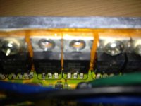
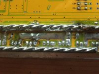
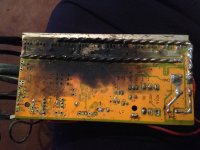
So here are 2 pics for you.

I just figured the marked resistors get really hot. Is that normal?
View attachment 1


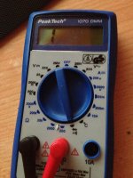
On the other pic I just wanted to clarify what setting I used to measure the Mosfets. I will measure again with your instructions dnmum. Thank you for those.
IMG_2801-2.jpg


I also measured the Hall sensors.

red -> black: 4.3V
yellow -> black: switching between 4.9 and 0V
blue -> black: switching between 4.9 and 0V
green -> black: switching between 4.9 and 0V

So I think those are ok.


The motor is a MagicPie MP-R270-12013041. I control this motor with the mentioned Crystalyte 72V controller in my topic.
It is not the mosfets causing the beeping. My multimeter is beeping as a result of a positive continuity test.

It took me some time to figure out what you exactly meant but now I feel I know the architecture of a mosfet a little better. So thank you for pushing me into this. :)
My measurements:

black on pwr vs phase
blue 520
green 030
yellow 520

red on pwr vs phase
blue off scale
green 004
yellow off scale


black on ground vs phase
blue 520
green 520
yellow 520

red on ground vs phase
blue off scale
green off scale
yellow off scale

Andy
 
So I figure I have to change the 2 high side Mosfets from the green phase wire? Just ordered 10 of the 4310Z ones.

Any ideas about the hot resistors? Is that normal or does it have to do with the malfunctioning mosfet and will go away after the exchange.


Andy
 
Exchanged the 2 high side mosfets from the green phase. Guess I wasn't lucky.

My measurements after the installation:

black on pwr vs phase
blue 481
green 005
yellow 483

red on pwr vs phase
blue off scale
green 006
yellow off scale


black on ground vs phase
blue off scale
green off scale
yellow off scale

red on ground vs phase
blue 485
green 488
yellow 496

Don't know what to do now. :(


Andy
 
Ok. Seems a little unsolvable. So any recommendations for a new controller with my MagicPie? 20" casted.

I would need max performance with my 20S battery pack which I could raise to 25S or 30S if this motor is capable to handle it.

Only connections I would need are: Power (obviously), Throttle, Halls, Motor Phases and some sort of connection for programming the controller.

I saw some forum users develop their own controllers but I am new and ist is kind of hard to get an overview on those. Especially as I am not very good at those electronic things.


Andy
 
I'm not invisible am I? Little weird that I don't get any answers.

I did some researching although this is not very easy as most of the controller related threads and wiki pages are outdated. So I figured the controllers from methods and Lyen are good but they are not selling right now. Or are they?

Are the controllers from em3ev any good? I would go for this one.


Andy
 
it is normal for the input power resistors to get hot. but you have to verify that the voltage regulator still can handle the high voltages by measuring the voltage on the output of the 12V regulator and the voltage on the input to the 12V regulator.

your green phases was shorted, that was why you got the .05V reading. since you replaced the mosfets it is still shorted. did you examine it to see what else may be causing the short? is the insulator intact on the mosfets? is the grommet allowing the screw to short the mosfet to the heatsink?

when you opened the case you can unscrew the screw and pull the mosfet away from the heat sink and then measure the body diode and if the mosfet was ok then you would know the short was from another source. just never saw your post.
 
Just a second before I got totally crazy I thought I could use 2 more of those mosfets I ordered. So I got rid of the newly installed ones and installed another pair. And now it's all working properly. So somehow the short was within the old mosfets and in one of the new ones too.

Thanks alot for pushing me again.

Now I only have to figure out how to install my wheel without the brakes scratching every full turn. Somehow it's not running round. Well thank you for your support again.


Andy
 
you can test them to see which out of the pair is bad by find the one you think is most likely the bad one and cutting the source leg only. then retest the mosfets and if the bad one is the one you cut then you can leave the other one in place and just remove only the bad one. but if the one you cut is the good one then you can solder the source leg back together and remove the other one.

the forward bias for the body diodes should be identical for all the mosfets. if you find some that are different then they are suspect.
 
Mosfet testing ...just worry about the first part on how to do it with multimeter.

http://www.4qdtec.com/mostest.html

with a mosfet out and on the bench this takes maybe two seconds each mosfet.

I am wondering if it is not a problem with the insulation between the mosfet and the heatsink bar.

My friend had a Crystalyte controller that from new, worked fine, but had a small piece of swarf that pierced the insulation strip with mosfet tightened down. It was only one MOSFET that was the issue, on the live side..so the case was live. Only became a problem one day when he decided to bolt the controller to the frame of the bike, and accidently shorted a negative lead from somewhere to the frame...big spark :) so maybe check the insulation strip behind the mosfets.
 
but why would you want to take the mosfet out? i don't see how this test can be used to test a mosfet while it is in the circuit. have you ever used it to test a mosfet in a circuit?
 
Like I said the problem is resolved. One of the mosfets I replaced was also causing a short and after changing the mosfet pair a second time everything is running now.

All I need to do now in order to get on the street again is change the cold weather outside and find out how in the heck I can find out why my rear brake is scratching every turn against the brakeholder or why my wheel is not running round. :)


Andy
 
dnmun said:
but why would you want to take the mosfet out? i don't see how this test can be used to test a mosfet while it is in the circuit. have you ever used it to test a mosfet in a circuit?

was not suggesting to use it in circuit, that had not even crossed my mind. I was thin king of the mosfets that are already out. The OP has mosfets that he has replaced, twice now, and the first set of replacements did not work either..so by my reckoning that makes 4 potentially good mosfets that are out and 'on the bench', assuming that the issue was a short caused by some other factor, like a poor insulator, swarf behind the mosfet etc.
 
Moya said:
... why my wheel is not running round. :)

Andy,

when you took apart your "Zauberkuchen", did you mark the side covers, how they came off?
You should assemble the side cover in the same way they came off to get it running round.

If not marked, unscrew the nine little hex bolts on one side cover, turn the side cover one hole
in one direction, screw three bolts in, test if it is running round.

If not, turn the cover one hole more...

It helps if you remove the clear silicone gasket stuff between cover and "rotor".
 
Thank you for your suggestion but I actually did mark everything before opening it. Should all be as it was before. The rear wheel is still wiggling while turning but I did manage to set my brakes in such a way they won't scratch anymore. Not getting rid of the wiggling problem, I know, which will result in my tire to wear off much faster.

Well at least I managed to order pure sunshine for the next few days.

Andy
 
90 F is pretty warm for Germany. I used to be stationed near Koblenz viel spass.
I think you should get a lyen controller 9fet as it helps to have a back up one so you can keep riding.
 
Sounds like you need to adjust (tighten/loosen ) some spokes to bring the wheel back in to round.

It is not difficult.just take it slowly Do a search for 'Wheel Trueing'

Only tighten or loosen the spoke nipples by half a turn or less at a time.

Turn the bike upside down..or some how suspend the bike from the seat post, so the back wheel is off the ground.

Now adjust the brake caliper so the brake pads just miss the rim most of the time, but just touch in a few places where is is a bit 'bent'
You will see in the video the man is using a special frame with calipers..but you can use the brakes for the same purpose

Rotate the wheel slowly by hand till it touches the brake pad on one side.

Note the point where it touches..this is where you need to adjust the spokes.

If the rim is touching the left hand side brake pad, you need to loosen a little bit, a spoke or two on the left hand side, and tighten the spoke on the right hand side, in between the two you loosened on the left. This pulls the rim to the right hand side.

It is slow and painstaking work, but not difficult, you just need patience.


http://www.parktool.com/blog/repair-help/wheel-and-rim-truing

http://sheldonbrown.com/tooltips/truing.html

[youtube]bcZ1jjB_AdQ[/youtube]
 
Been really busy the last few days so I just saw your posts.

@wineboyrider: My dad lives near Koblenz. Great coincidence. :)

@NeilP: Thank you for the ideas. Will check that out now.

@all: So my bike was working pretty good the last few days and I have been riding it daily. The weather is pretty consistent and it seems we will have some more sunny days here, so it's been really awesome getting a subway sandwich in the city and riding back up the hill to where I live.

So now the downside: Yesterday I had to push my bike up that mentioned hill for about a mile because it didn't want to move anymore. Turning the throttle gave a tiny tiny jump but the wheel wouldn't move anymore. So I thought that the battery was dead and was very surprised because I didn't really use it much going down the hill. Came back home. Measured the battery. All above 4.0V. So I did some troubleshooting. Throttle signal is fine, Mosfets were fine. Connected everything back together. Lifted up back wheel. Gave some gas to the throttle and *poof*. Think a Mosfet blew. Will check that after dinner.

Well this controller is only bugging me. So what should I get now? I want max performance. I was thinking of getting an 18FET-Controller with 4115s and upping my 20S to 25S or more. Are there any recommendations on what this casted Goldenmotor can handle AND which one of those many controllers is good quality? With programming option of course.


Andy
 
IMG_2902re.jpg

So I replaced the FETs again and those seem fine. Something else blew and I don't know what. Don't really care anymore though. I just want a new and reliable controller. Still figuring out which one would fit best for me.

And thank you for the links and video NeilP but I don't really have spokes. My wheel is a casted wheel with a Goldenmotor MagicPie. There must be something wrong with the way I installed it but I just can't figure it out. Placed the washers on diefferent positions along the axle without any luck. I guess I have to give it into a bikeshop so they can take a look at it. Hope they don't freak out over their first E-Bike. Those monsters are not very common over here.


Andy
 
Hi Andy..sorry, did not link golden motor with cast wheels as I have never seen one...but this is worrying.

When the wheel rim rubs against the brake, is it always rubbing on one side ? or just in certain parts of the rotation?

If it rubs all the time then that could well be a mounting issue..but if it only rubs occasionally, then it can't be a mounting issue..there is damage somewhere, either the bearing or axle..or the rim itself ..so the complete wheel has had a bash and is warped.

Think about it..if it is a perfectly circular disk, then the rubbing has to be constant if it is just mounted incorrectly.

So still try what I suggested, although you can't adjust the spokes. Turn the bike upside down and use the brake callipers in the same way the guy in the video uses the special callipers on the truing frame. At least then you will be able to see if the rim is running true.

Also get something like a pencil or marker pen and fit it to the frame with something like cable ties or a rubber band, pointing at any flat surface on the hub side cover..while spinning the wheel, slowly push the pencil towards the hub..see if it rubs all around or just in a few places.

If you find the rim is twisted, all is not yet lost. Take it to a locla engineering / machine workshop and see if they have a hydraulic press. If it is not too bad they may be able to press the rim straight again.
 
Back
Top