Cycle Analyst with Proximity Sensor Brake - POT [problem]

twist

10 mW
Joined
Feb 11, 2016
Messages
25
Location
Spain
POT01s.jpg

POT02s.jpg

POT03s.jpg

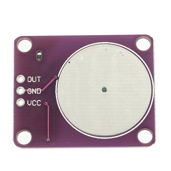
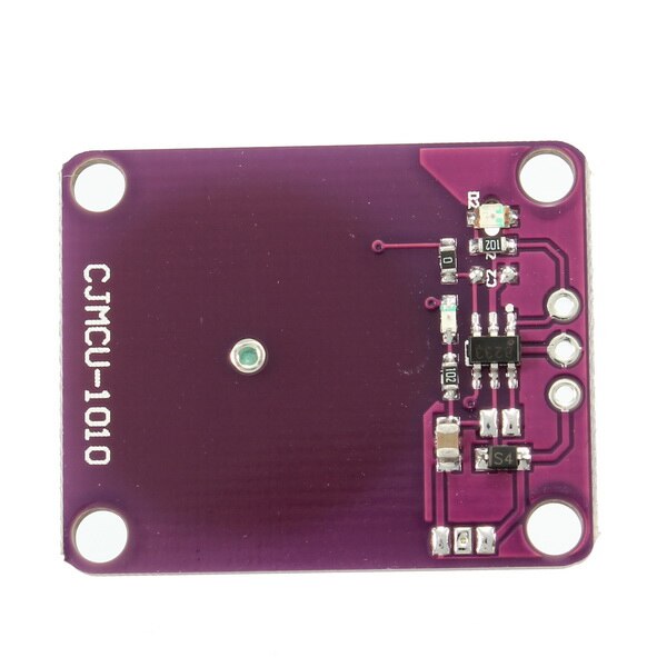
I first had a End-Stop switch with metal flap but that broke on my first test ride so I desided a Proximity Sensor (CJMCU-0101) for breaking would be the best idea and it is a perfect solution because I just have to get close to the brake to brake with regen :D

Now I have probably a wiring error (I'm also using 2 Cycle Analyst at the same time)! When I test it in my shop everything is fine but when I bike with it and engage the brake it will not turn off regen again and if I pedal the regen also engages :cry:

In the shop the regen brake turns on and off just fine!

I think it's just a small problem but I'm to tired to think right now. Maybe somebody has a hint :)

Cheers,
Christian
 
I put a Diode between GND and the brake and now it's a little bit better but still not usable.

Now the brake engages sometimes for a milisecond and the Throttle Out goes up to like 1.3v.

Maybe somebody has an idea. I'm guessing I have to put somewhere a resistor :roll:

Cheers,
Christian
 
If you can post the exact wiring diagram of how the relevant parts are connected, and list the settings you have in the CA, it would make troubleshooting easier.

Knowing which controller may also help, if there's something about how it works that could cause this.


Side note: If using a pot rather than a switch for an ebrake, it may have to be a very high resistance version, so that it is effectively an open circuit whenever it isn't engaged, and is effectively a short circuit whenever it is engaged.

If the pot is being used in some other way than as a direct replacement for a switch, you'll need to show that in the wiring diagram.
 
Thanks,

will try to make a wiring diagram.

Here are a bit more infos of the setup:
1 BBSHD Mid Drive Moter
1 C9 2707FD Front Drive Moter
2 Cycle Analyst
2 Phaserunner

The pot is just for setting the PAS - Levels.

I had the same setup running with just a switch for regen-brake and then everything was working fine.
I changed then to a proximity sensor for the regen and now it is sending the right signals only when I'm not biking.
When I'm biking the regen-braking get's activated every few seconds for a few milli-seconds.

Probably a problem with the proximity sensor?! It just workes so nice when you test it on the stand :)

EDIT: Just tested everyting just without the proximity sensor and then everthing is working. The sensor ist just connected with 5V - GND - SIGN.
HTB1hrtTSpXXXXaQXVXXq6xXFXXXL.jpg

HTB1A6ObSpXXXXaBXpXXq6xXFXXXR.jpg


Also for testing I added a Diode between 5V Brake - 5V Sensor and SIGN Brake -OUT Sensor.

Cheers,
Christian
 
twist said:
1 BBSHD Mid Drive Moter
1 C9 2707FD Front Drive Moter
2 Cycle Analyst
2 Phaserunner
So the original BBSHD controller has been removed?


The pot is just for setting the PAS - Levels.
I guess your title for the thread confused me, because it specifies POT right after the "proximity sensor brake", so I thougth the POT was for the brake, too.


I had the same setup running with just a switch for regen-brake and then everything was working fine.
I changed then to a proximity sensor for the regen and now it is sending the right signals only when I'm not biking
.
What speficially does that particular sensor do? Is it just a solid state switch? If so, then it should do exactly what the regular switch did, as long as it is wired the same way.


When I'm biking the regen-braking get's activated every few seconds for a few milli-seconds.

Probably a problem with the proximity sensor?! It just workes so nice when you test it on the stand :)
Sounds like the sensor either is defective or has a function where it "tests" periodically.

Also for testing I added a Diode between 5V Brake - 5V Sensor and SIGN Brake -OUT Sensor.
Do you mean on each wire a separate diode? Otherwise you'd have to directly short some sensor wires together, as a diode only has two connections.

Whihc polarity is the diode in each connection?
 
amberwolf said:
twist said:
1 BBSHD Mid Drive Moter
1 C9 2707FD Front Drive Moter
2 Cycle Analyst
2 Phaserunner
So the original BBSHD controller has been removed?

Yes, the controller is removed. It broke during a 5000km bike tour and right now I'm preparing for a 10000km bike tour and that is why I have 2 of each.


The pot is just for setting the PAS - Levels.
I guess your title for the thread confused me, because it specifies POT right after the "proximity sensor brake", so I thougth the POT was for the brake, too.

Sorry :). Just the proximity sensor is not working. I just wanted to show the setup because people sometimes don't know where to put the POT.

I had the same setup running with just a switch for regen-brake and then everything was working fine.
I changed then to a proximity sensor for the regen and now it is sending the right signals only when I'm not biking
.
What speficially does that particular sensor do? Is it just a solid state switch? If so, then it should do exactly what the regular switch did, as long as it is wired the same way.

Here the info to the sensor:
CJMCU-0101 SINGLE CHANNEL INDUCTIVE PROXIMITY SENSOR SWITCH MODULE
1. Operating Voltage:2.0V-5.5V
2. Max Power Consumption:11.5uA;low power consumption 1.5uA
3. External Configure Pin Set Multiple Modes
4. High Reliability:chip built-in anti-shaking circuit
5. Can be used on glass,ceramic,plastic surface
6. Size:30*24mm

It's like a solid state switch and I used it with arduino and there it was working just fine.
It also just workes fine as long as I don't bike :roll:

When I'm biking the regen-braking get's activated every few seconds for a few milli-seconds.

Probably a problem with the proximity sensor?! It just workes so nice when you test it on the stand :)
Sounds like the sensor either is defective or has a function where it "tests" periodically.

It depends on how I bike :) ... It's not a test coming from the sensor it is a interference with the Cycle Analyst.

Also for testing I added a Diode between 5V Brake - 5V Sensor and SIGN Brake -OUT Sensor.
Do you mean on each wire a separate diode? Otherwise you'd have to directly short some sensor wires together, as a diode only has two connections.

Whihc polarity is the diode in each connection?

Each wire has one diode.
POT04s.jpg

Thanks and cheers,
Christian
 
In my experience in the past, these are very sensitive circuits. I'm pretty sure you are suffering from FET switching electrical noise when the controller is in operation.

There is no information on the site about the output stage but assuming you have two in parallel, the diode on the sense lead makes sense to ensure the output is current sinking and will not interact with a second unit. An ordinary silicon part is okay although a Schottky would have given a bit better zero-state voltage margin - not worth changing.

There is no point to the diode on the +5V power lead. You might instead use a small value resistor (maybe 150 ohms - depending on the prx sensor current draw) and add a 0.01uf cap directly across the sensor power connections on the PCB. You could try different small value caps to see if you can bypass the noise spikes.

Although this is an interesting strategy, I will be surprised if it doesn't lock ON when wet. I would try that Use Case straightaway before spending any additional time getting it operational as it may be unworkable in any case - just a thought....
 
Thanks,

I will try that!

I just build out of the "Digital Aux Example" (https://endless-sphere.com/forums/viewtopic.php?f=4&t=37964&start=3150#p1196642) the Digital 2 Button with POT Circuit but have also now a small problem :lol:

POT_V2_001s.jpg

The two buttons are only working right when the POT is on the medium setting or higher. If the POT is on 0 then if I try to change something with the buttons it will go back to the 0 setting by itself. If the POT is on a little higher position then both buttons are just going up und i can not go down :roll:

file.php

R2/R4 are 5.05k because I didn't have 4.7k
D1/D2 are 1N5819 Diodes
POT is 5k ... just saw that it maybe should have been 10k?! but I also don't have one to hand :roll:

What did I do wrong? Maybe I should not work anymore with electronics or work more with electronics again :lol:

EDIT:
I'm getting the wrong V range:
POT 0 = 0.43V (should be 1V?)
UP = 0V
Down = 0.22V (should be 0.5V?)
Here the buttons are not working right!

POT 100 = 4.99V
Down = 0.23V
Here everything is working fine :D

With the original CA3_DAux (from Grin) + 5k Pot I get the following:
POT 0 = 0.85V
DOWN = 0.42V
Does only go down to 2%Asst

POT 100 = 4.99V
DOWN = 0.47V
Here everything is working fine :D

Cheers,
Christian
 
I played around a bit and with R2=182 Ohm and R4=23k I get POT 0=0,68V and DOWN=0,28V / UP=0V and everything is working.

Don't like that R2 is so low ... should there be a problem?

file.php


Cheers,
Christian
 
twist said:
EDIT:
I'm getting the wrong V range:
POT 0 = 0.43V (should be 1V?) --- this should be about 0.86V
UP = 0V
Down = 0.22V (should be 0.5V?) ---this should be about 0.43V
Here the buttons are not working right!

POT 100 = 4.99V
Down = 0.23V ---this should be about 0.43V
Here everything is working fine :D

With the original CA3_DAux (from Grin) + 5k Pot I get the following:
POT 0 = 0.85V
DOWN = 0.42V
Does only go down to 2%Asst

POT 100 = 4.99V
DOWN = 0.47V
Here everything is working fine :D

There is something strange going on here. The Vfwd curves for that diode look like this:


1N5819_FwdVoltageCurves.png

The CA uses 0.22V and 0.65V to discriminate the button pushes - based on Vfwd = 0.43.


SchottkyThresholds.png

The Vfwd for your diodes is 1/2 the rated value which means either the parts are defective or the resistances are 10 times higher than stated. (?)

At the end of the day, it doesn't matter how you achieve the target voltages (resistors, diodes) as long as they fall in 'safe' ranges so the CA can always tell what button is pushed, etc. A quick fix would be to series double up the diodes so that you got about the expected outputs. This is pretty much a hack to make it work without figuring out what's wrong, but it would do to get you riding. Otherwise, it looks to me like you are not pulling enough currnet through R2 to get the diodes up the curve. I'd try reducing R2 to 2.2K or thereabouts (parallel another of whatever you are already using). You can reduce this as required, but the draw on the CA regulator will go up (which we don't want). At about 5K it's 1ma, at 2.5K it's about 2ma, etc. The value on R4 isn't too critical but recognize that when the UP button is pressed, the POT wiper is shorted to GND so R4 is a current limiter when the POT is in the HI position at 5V. So here again, something in the 2K-5K range is fine, but don't go crazy low.

twist said:
I played around a bit and with R2=182 Ohm and R4=23k I get POT 0=0,68V and DOWN=0,28V / UP=0V and everything is working.

Don't like that R2 is so low ... should there be a problem?
Yes - This is not the proper approach. With the POT in the HI position, pressing UP will draw 5V/0.182K = 27ma which is huge. You should be reducing R2 to raise the bias current on D1 and D2 independently of the attached POT or switch. R4 is only a current limiter and should not be reduced to raise the diode bias current (to raise the forward drop).
 
Back
Top