Daly BMS LVC problem

bardbe

10 mW
Joined
Jul 4, 2017
Messages
21
Normaly if I get a failure on a device like a BMS, I would not publish it on a forum as it doesn't mean it's a bad product, and could give unfair bad publicity, but in this case I see this problem on 4 Daly BMS that I own, which makes me suspect it is a design issue rather than bad luck or misuse.

Last year I bought 5 Daly BMS from Dalystore at AliE: 2 14S 30A, 1 13S 60A and 2 10S 30A, all with separate charge port. The first time I triggered the LVC on the 13S BMS when my ebike battery was almost empty, it never recovered after stopping bike and trying to switch on display. Back home I measured some strange low voltages on charge- and output-port and my Grin Satiator refused to charge it. I thought it was broken, but removed it from battery and reconnected it again and it was normal again. Since then I have not triggered LVC on that BMS. The same applies to my 10S BMSes. On both the 14S BMS, I have triggered LVC a few times and they never recovered normaly without disconnecting battery, and after a 2-3 LVC even disconnecting did not get them back to normal, and I considered them faulty. I contacted Daly store, and they asked me to check voltage on all balance lines, which I knew was allright and not the cause of the problem. As expected they wouldn't admit that this could be a problem, so I suggested that they send me 2 14S BMS and I would pay for one of them. I selected the Common charge port this time to rule out if this was related to the Separate port design.

Turns out this BMS have the same problem. I have triggered LVC 2 times now (my commute drains my battery on one charge, so it's a bit unavoidable to not trigger LVC sometimes especially in winter), and both times I needed to separate battery and BMS to be able to charge it. Last time voltage was 44V which is above LVC. It hasn't failed so far, but expect it to happen later on as the previous two 14S BMS. Normaly one would expect a BMS to fail if driven too hard, but in this case it fails when current drain is low, probably less than 10A, and at low voltage. Hence it seems that the BMS is left in a logical state thats not healthy for it, and which it cannot recover from on its own.

All this makes me think there is a design weakness in the Daly BMS, and the reason for posting is to get feedback from other Daly BMS users if you have experienced the same or be willing to test it by draining battery to see if it recovers. It could potentially ruin the BMS, but then you know it doesn't work as it should, and we can then address this to Daly and hopefully get it improved.
 
This is kinda hard to follow... but any BMS once triggered to shut off, won't turn "ON" again until the pack meets normal parameters. In fact, usually the recovery parameters are actually normally more restrictive than the shutdown ones. So a sufficiently discharged pack, not meeting the "normal" requirements will stay "OFF" until met.

There have to be different levels. Otherwise, the moment a cutoff threshold is reached, and the BMS cuts power, it would immediately reconnect. The "restore" power threshold is designed to make sure you've fixed the problem before resuming normal use.

All that said...I have a Daly in the box. Never used it. So I'm not a Daly expert.

Ideally, the "normal" use parameters need to take cold weather into the shutoff calculations so they don't shutdown power prematurely. But for the very basic pack BMS's we use, they aren't especially intelligent enough to do that.
 
This sounds like a safety feature, in that it helps prevent damage to the cells that some people have done by riding a pack to "empty" and then waiting till it recovers enough to turn back on, then doing it again and again until the cells pass out from exhaustion. ;)

Some BMSs have a reset button or jumper, so that if something goes wrong you can reset the CPU. Others require you to connect a charger to them to reset it.

PITA, but it's safer for the cells to have one that doesn't "recover" from a low cell voltage event that triggers the BMS protections. Shouldn't matter for an overcurrent event, since those should be safe to auto-reset from.
 
Thanks guys for the input, but as I said 2 of the BMS are broken and it happened after LVC. I disconnected BMS and recharged battery, but not working when plugged in. The BMS is waterproof and has no buttons for reset or LEDs indicating a failure. As it was/is I couldn't charge battery with BMS in circuit because charge port voltage was way low, like 28V or something, and my smart charger did not accept it.

I know there should hysteresis in the off/on voltages, but it should not be a big difference. I had a store battery before which triggered LVC, but it came back after a short cool off as voltage will rise 2-3V after load is off. The battery was never depleted and a well designed LVC should recover at least the first time it triggers and thern only shutdown if battery is further depleted.

I understand that it's hard to believe that a big brand like Daly have this issue, but this is my experience and I'm reaching out to the ES community for people who actually have this BMS and can test the LVC to see if it behaves like this.

PS! Cold weather is not the issue here, as this happens in summertime also
 
bardbe said:
Thanks guys for the input, but as I said 2 of the BMS are broken and it happened after LVC. I disconnected BMS and recharged battery, but not working when plugged in. The BMS is waterproof and has no buttons for reset or LEDs indicating a failure.
You might not be able to see it thru whatever waterproofing there is, but there's probably some pads on the board for a reset switch or probe, though they may not be labelled as such. Optionally, if the spec sheet can be found for the MCU chip they are using on there, you can find which pin is reset on it, and manually wire in a button (usually this just grounds the Reset pin momentarily to restart the CPU).


As it was/is I couldn't charge battery with BMS in circuit because charge port voltage was way low, like 28V or something, and my smart charger did not accept it.
Then in that case, there is indeed a problem, because the BMS shouldn't be shutting off the *charge* port, only the *discharge* port, *unless* there is a cell group that has dropped below the safe lower limit that it's designed to not allow recharging at. A low voltage like that isn't really a "voltage", it's just leakage thru the mostly-shut-off FETs. If you put any load on it at all, it would just drop right to zero. If the pack were *really* that low, it would have damaged cells. ;)

If there's a group that happened to dip below that, even momentarily, it's possible that the BMS would "brick" the battery to protect against the possibility of fire during recharge or later use of a pack with a "damaged" cell. It *shouldn't* do it for a momentary drop below that point, only for a cell that *stays* below that, but it might not be programmed that way (software bug).

If that's the case, it is something Daly could fix with a software update, if the BMS is field-programmable (rather than only in the factory). But you first have to get them to care, then to understand the problem, then to generate a fix that has been tested not to break anything else. ;) In my experience with most companies of any kind, that's a long drawn out process if you can get it started at all.


I understand that it's hard to believe that a big brand like Daly have this issue,
They can all have issues; QC is not really much of a thing for many companies, not just in the manufacturing, but also in software development, so it isn't a big surprise when serious bugs sw or flaws in hw design or build show up. :(
 
I think now...you are suggesting after a single LVC event, the Daly BMS fails permanently. That's possible but like you mentioned unlikely to be true in every case given the popularity and widespread use.

Only controlled tests can validate the theory.
 
Amberwolf, you are such a helpfull guy! Wow! Very nice of you to come up with suggestions although this particular BMS is hermetically sealed. I tried to find a way to open it, but gave up, and I doubt I find any reset optons inside either. These BMS looks the part, but at $25-35 are rather cheap although cheap BMS usually fail to supply advertised current, not fail at LVC at 1/3 amps. My packs are balanced so no cell-group too low either. Again, no theory helps solving this mystery, only user feedback from other Daly user can really enlighten me. If there is only one that experienced this, I'm good. Then I might be on to something. Without that I'm at a loss of ideas. Even if I don't get an answer soon, there will potentially be people searching for this in the future. I for sure have lost faith in these BMS and will not replace them with these Daly models if/when they fail. They have some Smart BMS also now, which is probably better, because you can check state with BT.
 
BlueSeas, where did I write it fails permanently after one event? I wrote that 2 of them failed after 2-3 hangups, possibly 3-4. In any case you are not really helping here other than being suspicious to my claims. I wrote that I'm not the type that goes crazy on the forums to bash stuff that disappoints me. If it's stuff thats cheap and expected not to last then I don't bother, but Daly seems to be a large and serious BMS vendor and I took a chance to opt for this brand for my batteries (somebody should make a review thread on "all" BMS on the marked). When they disapoint it's fair to ask others about it. You said you had a Daly BMS, so if want to be of any use in this thread, hook it up to a battery and go for a ride until it triggers LVC, perferably while putting some amps through it. Thanks.
 
bardbe said:
BlueSeas, where did I write it fails permanently after one event? I wrote that 2 of them failed after 2-3 hangups, possibly 3-4. In any case you are not really helping here other than being suspicious to my claims. I wrote that I'm not the type that goes crazy on the forums to bash stuff that disappoints me. If it's stuff thats cheap and expected not to last then I don't bother, but Daly seems to be a large and serious BMS vendor and I took a chance to opt for this brand for my batteries (somebody should make a review thread on "all" BMS on the marked). When they disapoint it's fair to ask others about it. You said you had a Daly BMS, so if want to be of any use in this thread, hook it up to a battery and go for a ride until it triggers LVC, perferably while putting some amps through it. Thanks.

I missed the 2-3 hang ups before failure if posted previously. The Daly BMS I have, was purchased as a backup, for a BT BMS. Both from China, where the lead times are long, and the quality not consistent from one brand to the next. The BT one met my requirements. To wire in the Daly and test, well that's outside the scope of forum support.

I'm not suspicious that you had failures, I take that as a given, but the question is why? I don't know. Anymore that you do. Can only speculate.

I kinda suggested cold weather. But you disagreed. OK. Maybe the increased current flow at lower voltages. It's at best a maybe.

Wish I had the answer, but I don't.

Good luck. Hopefully someone will.
 
Crossposted from another Daly BMS question thread, in case anyone with one wishes to try testing this potential reset-without-a-charger fix:

I had a thought (quick, get the fire extinguisher! ;) ):

This *should* work, if the BMS shutdown is the reason I think it is (it turning off it's own internal power converter, which is what keeps itself "on", kinda like a latching relay setup).

Wire a NO SPST momentary switch from main cell battery positive to the charge port positive. You can install a large-value (10kohm+) resistor in series with the switch if you like; this will ensure there are no significant currents flowing. Probably just a 1kohm would be sufficient for that, possibly even less.

It is possible (but unlikely) that you may *also* need a switched wire from main cell battery negative to the charge port negative, in which case you'd use a NO momentary 2PST (DPST) switch. Depends on whether or not the BMS has any internal ground from it's own internal power converter to the main cell battery negative or if it only goes thru the charge / discharge FETs.
 
BlueSeas: Of course not. I had to make connectors on my BMS to easily unplug it, so in case you dont plan to use the Daly, don't bother.

amberwolf: Ha,ha! It would be interesting to test your procedure, but from previous experience of how much energy those batteries contain, I'd rather not :D Besides I'm not really interested in troubleshooting the unit, because I'm not gonna try to make a fix for the problem, and it's not something that's practical to repeat every time it locks down.If there is a problem, which in my opinion there is, Daly should make a fix themself, or expect to loose customers, at least the ones reading this post. Since I haven't received other experiences yet, I will not recommend against it, as it's possibly as good as any other BMS in it's price range performing the other functions a BMS do.

So far I only got response from you two guys which I appreciate, but no feedback from Daly users about experience of LVC behaviour, hopefully some are testing now... :wink:
 
I've had a couple of BMS boards that would hang when triggered and you had to charge through the discharge port to get it turned on again. Completely unplugging it and reconnecting would also reset it.

Most BMS boards have the P+, C+ and B+ all connected permanently together. Switching all happens on the negative side.

I did something like Amberwolf suggested, where I installed a push button switch and a 1K resistor from B- to P-. When the BMS trips, now I can just push the button to reset it. Saved me more than once.
 
Hmm, on a second thought, the amberwolf/fechter fix could come in handy if it turns out my current 3 BMS setups that are still soldered in circuit has a LVC hang-up. The two new BMS I have connectors to unplug if that happens. The BIG question is though: The two BMS that I completely removed from battery and reconnected a couple of times WITH hang-up still being present, could they be recovered by doing some "tricks"? I'm no expert on BMS internals, but have serious doubts about that, and I threw them away so cannot test it either. In that case, there is a HW damage to the BMS, and when that happens I cannot trust the BMS anymore, and I start worrying if it will fail in other parts as well, like balancing, which is the main reason for me using a BMS (I do measure cell V once in a while though). Since Daly is such a large company, one would expect bettery quality, as this is not a costly feature to make right if the designer is aware about it. Again if I'm the only one experiencing this, it's not gonna be fixed. Not the end of the world :)
 
Hard to say without testing. It's possible they might still work if reset by connecting the B- to P-, but also possible something fried and it's toast.
 
I have been facing a similar issue where the batteries, once hit the LVC, are not able to reset and start charging. I'm not understanding the reason, I tried 2 different Daly BMSs, one was 15S 50A and other 15S 40A. My cells are balanced. And they did go for an initial charge when the batteries were at 60% SoC, and discharged till LVC happened. But, after it, there was no charging happening. I check the B- and P- ports too. The B- is showing close to 41V whereas, the P- shows 20V, which is a major issue. Any suggestions on what can be the possibility here shall be helpful.
 
Try what I posted just above. You can also try charging through the discharge port. If that doesn't do it, you need to measure the individual balance line voltages and look for one out of whack.
 
fechter said:
Try what I posted just above. You can also try charging through the discharge port. If that doesn't do it, you need to measure the individual balance line voltages and look for one out of whack.

How does charging through a discharge port wake up a BMS even if the battery is at 93%?
 
Once the BMS trips for whatever reason, most of them are looking for the discharge port voltage to come back up to near pack voltage to reset. If the load (controller) is disconnected or turned off, a resistor in the BMS is supposed to bring the output voltage back up to where it can reset. This is a safety feature to prevent the BMS from turning on against a shorted load. The problem is some controllers take a little current even when they are turned off, just enough to prevent resetting. Even if the controller is disconnected, I've seen some that just can't get the output high enough to reset (bad design or construction).
 
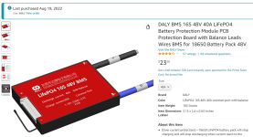
Here is the DALY I am working with, and here are the troubles I have had

DALY_001.png

At first I was in love. Quality seems so high

* Potted Assembly
* Simple Common Charge/Discharge (what you need for solar)
* External temp probe
* Clean, compact, quality wiring whip
* Nice and functional external probe
...

I could go on right? We all see how well they did it. The quiescent current is so low, everything seems perfect (except for not being able to program it)

Right?

PXL_20221112_010515193_compress87.jpg

So... I had some experience with very high current 4S units, and another brand that looks identical but with a different name

THEN
THEY STARTED FAILING

Failure Mode
Output mosfets shorted like diode

Indicator of Failure Mode
Does not stop for LVC (tho it tries)
Runs VERY HOT, far hotter than normal
If powered down you can actually measure this diode pass-thru from Blue to Black

I.E.
With a NEW unit in GOOD order you get OL (Open Circuit) between the Battery and Pack lines. Once in Failure Mode you get a Diode reading, anode pointing away, so basically... allowing any ground to return while dumping 500mV. This (at 30A) puts 15W of heat on the tiny device...


SO
HOW WAS IT DESTROYED?

Good Question

....
 
SAMPLE SIZE
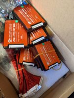
15 Units purchased on Amazon, but not prime. They had to come direct from China.

They came with certificate of inspection and stickers on each. I believe they pass, because when I first test them they pass! NOW... WHAT TEST DO THEY PASS... that is different question we will be working toward.

I PROPOSE
"They work until you get a heavy cut-out event"


I have a lot more to test, so I can scientifically prove this. They only cost like $25 each, so I am willing to spend a couple hundred dollars to prove that DALY populated (at least this run) with substandard mosfets.

SO
* 8 are new in box
* 2 are destroyed running hot
* 5 are built into packs like ticking timebomb :shock:

The first failure I saw
I was trying different corner testing. I am thinking that it is H E A T that destroys these units. Let us generalize

* If you put the unit into a configuration where it is allowed to reach temperature XXX for YYY long, it will be destroyed

You would think that the unit would protect itself, YES? I have tested the EXTERNAL temp protection and it works. I propose that the INTERNAL protection is either not implemented or otherwise does not work.

How to prove this?
Just overheat the unit.
For these, they are rated for 40A continuous and they are supposed to blip you off at 60A. If you run one up to 40A, and then creep the current for a burst at 60A, they will certainly fail before they self protect. If they have self-temp-protect, then the heat-up is happening too fast for the thermal mass to pass it. If they dont, well, the mosfets just reflow internally and turn into diodes.

SO -> H O T

That is what I am thinking/finding. That is the commonality between the two units I have here which are in a destroyed condition. They bot got H O T

So
Why am I bitching?
 
Well
You cant fault the BMS if you somehow drove it HOT without it being on to protect itself, but that is impossible. You could only do that in the event that the unit is ALREADY DAMAGED. Because - if balance taps are removed, then output is open, so no current can flow and you cant overheat

SO
The good test

* Remote Balance Tap Connector
* Attempt discharge while monitoring case temp

If it works at all, you have a BMS in failure mode.

Exact Link to Purchase (NON PRIME)
https://www.amazon.com/gp/product/B0876ZT5M1

You have to scroll down, but the datasheets are there. There are mistakes in datasheets (as always) but they describe use case that I have not exceeded. Very miffed... :kff:

-methods
 
Are those single port?

Another common failure mode is when the FETs try to turn off for a fault condition under high current discharge. If the turn off time is too slow, it blows up. Or you could have an inductive voltage spike on turn-off that blows it up.

Most common failure I've seen on similar units is from connecting the positive battery terminal before the balancing wires or having the higher cells on the balance connector make contact first. This puts multiple cell channels in series with no balance connections and can allow excessive voltage to blow up the shunts. This usually causes one or more channels get stuck on shunts and slowly bleed the cells. This doesn't seem to be what you are describing.

If the temp sensor is accessible, you could try heating it with a heat gun to see if it turns off the output.
 
Agreed on high current discharge termination killing the mosfets real fast, due to insufficiently fast turn off.

Agreed that inductive flyback would kill mosfets if they are like 63 volt for 58V application. I see pads for really big TVS diodes but they have learned that they can non-pop these.

Temp Test
We have two temperature probes... Presumably. The one hanging external and I would PRESUME one on the PCB. I just recently tested the external one by warming it while running a 40A continuous discharge.

Either then
Or shortly after that (we can repeat the test) the output mosfets failed

So
As far as I can tell
The unit is trying to click on and off, but it's mosfets are already in fail mode, shorted.

Or
Since this is the common ground unit... It's very possible that the two mosfets are back to back. In this case when one fails short, we go through the body diet of the second.

We are about to find out
But I cannot run your test because the output no longer functions. I have a second thread going where I'm going to do a teardown.

Anyway
It's nice to see you. Look how far things have come*

-methods
 
Second Thought
I will set up the camera and show that a unit works at low currents like 5 amps

I will then thermally shut it off five times at 40 amps. I bet that it is destroyed.

-methods
 
TEST RESULTS

By request of Fechter
Who, btw, you should know.... is the most helpful damn guy on the planet. Back when I did not know which end of the battery to sit on, fechter was explaining the basics to me. I can remember no fewer than 20 instances when I was holding on to inaccurate or outdated information ---> and fechter set me straight.

PXL_20221113_132941400_compress69.jpg

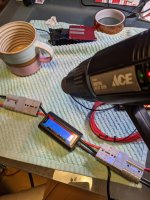
Here is the test requested above.
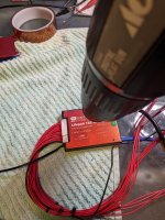
"Heat UUT with a heat gun to see if it actually turns off when it gets hot"

Right? Since that was the assumption (Assume = Ass U me = Ass of You and Me)

PXL_20221113_132629675_compress2.jpg

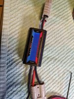
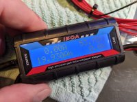
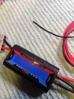
I am using the Ghetto clap-trap shown above since I have not had a CA in years. This piece of junk is total and absolute garbage. You may notice a USB cable coming out of the side, that is what I had to do just to have it persist in memory. The Wh gauge is completely broken and rolls over. The readings are +/- AMPS -> So DONT DO IT.

* Just buy a CA

In fact, I will by any used (but functioning) early model CA right now. I have budget for 5+, maybe 10pcs. So if anyone wants to upgrade, I will buy your used unit IMMEDIATELY and even send you a shipping slip to make it easy. (cough)

Yep - those are counterfeit Anderson SB50, I have counted at least 3 brands mixed at Amazon

PXL_20221113_132658316.MP_compress21.jpg

So anyway
Since I dont have a CA (COUGH) I plug this piece of crap into the wall with a USB cord that I hacked in. You can see yesterdays 19Ah still on the meter. What we are going to test first is

EXTERNAL PROBE

PXL_20221113_132833954_compress44.jpg

Ok, test took like 30 seconds. UUT shuts off almost immediately, as expected. Notice that we are doing this at like an amp or two, that is the current necessary to run my SPF 5000 ES + Auto Transformer, so burn-current.


PXL_20221113_132847070.MP_compress93.jpg

There is the result above, CLICK. When you see the screen glowing but no numbers, that is when there is no HV on the plugs and only 5V USB holding memory.

NOW
On to the real test

View attachment 4

Same picture as at the top
TOTALLY LAME RESULTS

* Heated up UUT until the top aluminum was so hot it burnt my fingers
* Heated up the bottom potting until it got tacky
* UUT did NOT shut down, repeat DID NOT

To prove it was still operational
* Moved heat gun to the external temp probe
* Shut down almost immediately

Sigh...

-methods
 
Back
Top