
Done - with current rollback. CA V3.Gab said:Hi justin do you plan on ever putting a thermistor input on the cycle analyst ? it would be a really cool feature if we could see motor winding temps on the screen and also then if we could use that to do current limiting. that would be awesome. is that possible ?
You are using an out of date browser. It may not display this or other websites correctly.
You should upgrade or use an alternative browser.
You should upgrade or use an alternative browser.
Definitive Tests on the Heating and Cooling of Hub Motors
- Thread starter justin_le
- Start date
speedmd
10 MW
liveforphysics said:speedmd said:Some interesting reading on the emissivity of aluminum / finishes topic.
http://www.molalla.net/members/leeper/coatbar.htm
http://www.infrared-thermography.com/material.htm
Rougher surface / more area / more heat loss. Anodize looks to be very good change for aluminum in this respect also.
That surface color difference is making a larger difference than I would have imagined at such low temps.
Looked at the changes in coefficients a bit more and noted that the anodizing process by itself appears to be making more difference than color. Un colored Oxidized Aluminum surface is very high also. When looking at parts after the first step in the anodizing line, it seemed obvious what was going on here. The acid pre wash dulls the finish completely and greatly changes the surface. Acid baths eat into the surface. Top two picture show the surfaces done with the more common processes.
Justin has listed some good estimates IMO as to where the highest levels of cooling benefits will be gained. IMO on cooling of small units, Conduction is most always a primary factor, convection next most important, followed by radiation. IMO, Oil here is effective because it improves conduction. Great topic and certain to give us all some serious insight as to what is best path to take. Thanks Justin, Look forward to more testing.
itchynackers said:Justin,
Can you make any recommendations yet as to whether using an internal temp probe/thermistor is an advantage over using the "hand method" on the covers?
That's a bit of a silly question. It's like asking if I think it's and advantage to use a multimeter to measure a battery voltage over licking the terminals with your tongue. Well obviously if you want to know a stator temperature there is an advantage to directly measuring it with a thermometer over inferring it from touching a largely decoupled piece of metal with your hands! As for recommendations, for the 99% of ebike users who keep within a reasonable power range for their hub motors there is really no need for temperature sensing at all. It's just that this forum has a very disproportionate representation of that other 1%. Hence it may seem from reading ES that there is a widespread motor overheating problem that needs to be solved, but that's not really the case at all.
Anyways the goal of these experiments is just to get meaningful empirical test data to share on the subject, and then let the data speak for itself. There is one thing a bit related to the "hand method" that I am very curious about which I will get into later. And that is determining how much one can infer about the stator temperature from looking at only the casing temps, and more specifically the rate of change of the casing temp. It's a topic Methods and I have discussed since it could provide a reasonable means of doing thermal rollback with a small IR temperature sensor pointed at the shell, which doesn't require either sourcing or modifying a motor with a temp sensor built in.
John in CR
100 TW
justin_le said:... There is one thing a bit related to the "hand method" that I am very curious about which I will get into later. And that is determining how much one can infer about the stator temperature from looking at only the casing temps, and more specifically the rate of change of the casing temp. It's a topic Methods and I have discussed since it could provide a reasonable means of doing thermal rollback with a small IR temperature sensor pointed at the shell, which doesn't require either sourcing or modifying a motor with a temp sensor built in.
As the only one I know of using their hand to gain knowledge of their motor's limits, or certainly the only one who's suggested using it, I guess this is thrown my direction. I was surprised as hell to see Methods talking about using an IR sensor on the outside. While I've used my hand to check my ebike for years, not just motor, but controller and batteries too, I started doing it to gain an understanding of what's stressful to my system as well as just a general check for problems, like checking your oil on a car. eg If your battery has a spot warmer than the rest of the pack, attention is required. You notice a new noise from your motor and the motor is generally the same temp as usual after a ride, but the axle on one side is significantly hotter, then it's pretty sure you've got a bad bearing. I use it a bit like an experienced mechanic uses his ears to develop a knowledge of how well an engine is tuned, or in a car I often know that a car is starting to run hot because I can feel extra heat down by my feet before the idiot light goes off.
As far as knowing the stator temp enough for a thermal roll-back, that seems pretty risky for me based the data you've provided above. The relationship must vary pretty widely, so could end up rolling power back too early or too late. I've used shell temp by feel on a wide variety of motors, and haven't had a thermal failure yet, but if mine had the roughly 2:1 relationship you demonstrate at 300rpm, I'm sure I would have had at least one failure. I'm pretty sure that rpm plays a big roll in the stator temp/cover temp relationship, and that higher rpm reduces it. As support for that view, the motors I use now have a 95° thermistor on the stator. I've only tripped it once and the motor had a shell temp between 65° and 70°, which is quite different from the 120°C you testing at 300rpm. My warning light came on right after I ran the motor hard at 700-800rpm up hill for a couple of kilometers after saturating the stator with heat in stop-n-go traffic.
Spin your test rig up to a much higher rpm and see if the relationship changes.
John
PS- There are some circumstances that I can gauge stator temp with some accuracy using my hand at the covers. After a monster blast up a steep mountain climb my son and I did on video. The temperature of the shell near the perimeter was right at 37°C (cooler nearer the axle), and the stator temperature couldn't have been much different, and certainly not hot at all. The reason I can say that with confidence without being able to touch the stator is that I couldn't feel any warm air rising out of the exhaust holes on the vented motor. Also, after a few minutes I felt the motor again and it was still body temperature, still with no warm air rising out of the exhaust vents. That was a nice cool early morning with a high speed blast up the mountain, so fast I got 4 or 5% regen recovery braking for curves on the way up the mountain. In every day riding, especially slower stuff in traffic the motor gets warm and I can clearly feel warm air rising from the vents, though never like a sealed motor. The covers on that vented hubbie never get past 50-55°C. They quickly got to 65-70° during the short time I ran it sealed. That was the last typical efficiency hubbie I'll ever buy.
speedmd
10 MW
It would be great if someone in the group could possibly 3d model the heat flow of a test motor. We could then possibly see (and design around) the hot spots.
Some heat flow related reading on electric motors.
http://www.cedrat.com/fileadmin/use..._magnetic_and_thermal_analysis_for_motors.pdf
http://www.motor-design.com/papers/motor-cad_iemdc_2003.pdf
http://www.stanford.edu/group/uq/pdfs/journals/jfe_heat_06.pdf
http://www.m2netlab.wlu.ca/research/publications/EJ-52.pdf
justin_le said:[ It's just that this forum has a very disproportionate representation of that other 1%. Hence it may seem from reading ES that there is a widespread motor overheating problem that needs to be solved, but that's not really the case at all.
You mean not everybody is trying to run their motors at 5x the rated power?
I guess you have a valid point. If the cooling works well enough and the power input is limited to the right level, then overheating should be a non-issue. But that's no fun...
Here is a repeat of the first test that I posted, only now with the external fan blowing at about 12kph on the motor. In this setup, the motor has both side plates drilled out in a simple circular pattern of nine 3/4" holes, at about 2.5" radius from the center. In the first run, both side plates had their holes covered up with tape. In the 2nd run, the tape was removed on one cover but not the other, and in the final test both side cover vent holes were open:
View attachment 3
You can see that the transition from no holes to holes on both side covers resulted in a 2 fold increase in the amount of time it took before the stator reached 125 oC, from 20 minutes to 40 minutes. Meanwhile, drilling out just one side cover resulted in a much smaller improvement, to 24 minutes. It's also interesting is that the final side plate temperature at the time that the core reached the thermal limit in all cases is ~55-56 degrees. That implies that even with the air flowing through the motor, there is still roughly the same air temperature inside the hub, and that the overall conduction from the stator to the shell is the same. If the internal air was much cooler, then we would have expected colder side plates in the tests with the vented holes.
In order to model the effects of airflow, the simplest approach is to add one more heat conductivity term R3 from the stator directly to ambient, effectively bypassing the side plates:

By leaving the original values for R1 and R2, I found that the hole vents on a single side plate resulted in an effective 1/R3 value of 0.15 W/degree, while having both sides drilled out resulted in a much larger 0.55 W/degree of heat conductivity from the stator directly to ambient.
Here's how the model looks for the undrilled side cover if subject to the same conditions as the test with both plates drilled out:
View attachment 1
And here it is with the addition of a 0.55 W/degree heat path from stator to ambient, you can see that the model fits quite nicely:

So, it seems this simple first order R3 term does an adequate job of quantifying the effect of air cooling, and I'll be using it as the metric for comparing the performance of the different ventilation strategies going forwards.
-Justin
View attachment 3
You can see that the transition from no holes to holes on both side covers resulted in a 2 fold increase in the amount of time it took before the stator reached 125 oC, from 20 minutes to 40 minutes. Meanwhile, drilling out just one side cover resulted in a much smaller improvement, to 24 minutes. It's also interesting is that the final side plate temperature at the time that the core reached the thermal limit in all cases is ~55-56 degrees. That implies that even with the air flowing through the motor, there is still roughly the same air temperature inside the hub, and that the overall conduction from the stator to the shell is the same. If the internal air was much cooler, then we would have expected colder side plates in the tests with the vented holes.
In order to model the effects of airflow, the simplest approach is to add one more heat conductivity term R3 from the stator directly to ambient, effectively bypassing the side plates:
By leaving the original values for R1 and R2, I found that the hole vents on a single side plate resulted in an effective 1/R3 value of 0.15 W/degree, while having both sides drilled out resulted in a much larger 0.55 W/degree of heat conductivity from the stator directly to ambient.
Here's how the model looks for the undrilled side cover if subject to the same conditions as the test with both plates drilled out:
View attachment 1
And here it is with the addition of a 0.55 W/degree heat path from stator to ambient, you can see that the model fits quite nicely:
So, it seems this simple first order R3 term does an adequate job of quantifying the effect of air cooling, and I'll be using it as the metric for comparing the performance of the different ventilation strategies going forwards.
-Justin
John in CR said:Great work Justin. I just can't get over how cool the shell is staying with what I consider to be a hot stator. I say hot because if you park that's 120° a millimeter or less away from the magnets roasting away at them.
Yup. To check I used a handheld IR temperature sensor around the motor and the readings in all areas of the side cover and the rotor ring were within about 2 degrees, so the assumption that the magnet temperature is fairly close to the side plate temperature while running seems valid. Once you stop and park, then the resistance from shell to ambient will probably increase a lot because there is no convective air flow, and then that would result in the rotor and magnet temperatures increasing some before they cool down again.
Your results are showing a much higher R1, thermal resistance through the air inside the motor, than I would have expected. I think my better results with sealed hubbies similar in design to the 9C are due to higher rpm, which thru greater turbulence and wind resistance inside would greatly reduce R1.
I've just finished a test with closed holes at 400 RPM, and tommorow I'll run it at 200 RPM, so then we will have the effective R1 at 200, 300, and 400 rpm which should give us a good indication of how it varies with speed. And the plan would be to later on try repeating that with a pair of side plates that don't have any internal holes, but instead just have additional fins inside to help stir things up.
In the meantime though, this is what I've been preparing:

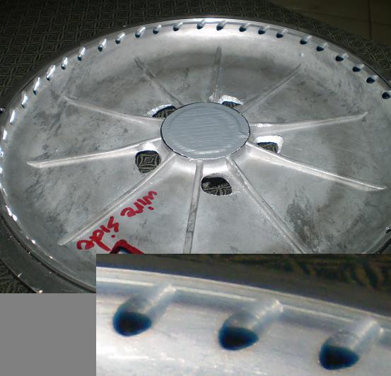
I've now got two 9C side covers, both with roughly the same vent hole area but one of them machined with 30 small holes to increase the "fan blade" effect as you suggested, and another with just 10 much longer slots which would offer less resistance to the external air coming from the fan (equivalent to forwards motion on the bike). So, we'll see what kind of difference if any exists between these two approaches:

On the insides, you can see that there are some shallow ribs in the 9C motor plate casting that should offer some level of fan effect. The plan will be to compare the results as depicted and with the addition of additional glued-in blades, to see just how much of improvement the blades make.
View attachment 1
It's really just more evidence against big wheels on hubmotors. If you extrapolate your results even an 80kg person with a 40kg bike with 26" wheels is going to melt his 9C on just a 5% grade. Just like wind resistance goes up exponentially with speed, a similar thing will apply inside the hubmotor and makes it better reject heat simply by running a smaller wheel at the same speeds. Higher speeds help even more in terms of heat dissipation by reducing R1 further and R2 as well.
Not to mention too that a smaller wheel diameter means you can achieve the same thrust with less torque, and hence less I^2R copper losses for the same accelleration, hill climbing etc. But in spite of all the electrical advantages to smaller diameters, there are a lot of practical reasons why larger wheels are nicer on a bicycle, and weighing that into the equation it's no surprise that 26" dominates smaller sizes by a very large margin.
i've pondered adding heat sinking instead of drilling holes and allowing dirt/mud/etc into the motor...
my RC bike astro motor benefits greatly from a huge aluminum heat sinks... a late night drunken thought.
my RC bike astro motor benefits greatly from a huge aluminum heat sinks... a late night drunken thought.
John in CR
100 TW
Justin,
A problem you're likely to run into with improved ventilation is the R1 & R2 will become unreliable, because the shell will have different temps and different areas. Was is the Watts scale on the right, watts of heat rejected?
Where and how are you measuring temps on the shell? On my motors with my more successful cooling efforts, the warmest part of the shell is always at the perimeter and between the spoke flanges. I assume that is from being unable to generate good air flow through the gap and/or the flow that does get through the gap has already been warmed while passing over the end windings on the intake side before entering the magnetic gap.
John
John in CR
100 TW
justin_le said:
Eeek. It's fine for the test, but I hope no one copies the intake holes. Don't you think the holes near the axle weaken the cover too much so close to the axle? I haven't done it his way yet, but I'm sold on Zappy's approach to intake, which is many small holes all over the intake side reaching out to a radius within about an inch of the end windings. That results in substantial intake area without allowing big stuff entry or some ass jamming a stick or something in the motor while parked. If you're going to try a one sided intake and exhaust out of the other, maybe do the intake only cover you'll need using Zappy's approach.
I'm about to try one with long radial slots for the intake, cut with a thin angle grinder disk, but I have no results yet. It also has slots with threaded holes next to them at the end windings. Their purpose is so I can install and adjust the blades from the outside with the motor fully assembled. That way I can evaluate how much difference interior blade count makes to the flow, and also to get the blades adjusted so they reach as close to the stator as possible without rubbing. I can also try different blade angles and shapes to determine their effect on flow and noise. I haven't seen it mentioned but vent holes result in much more noise from the stator. Cheap sine wave controllers can't come soon enough.

John
Hyena
10 GW
Fantastic work Justin, leave it to you to properly test and document what many of us have been fiddling with for ages - with varying degrees of claimed and/or demonstrated sucess!
As I started reading the thread I instantly thought you needed a small fan blowing on the side covers (or more correctly towards the magnet ring as would be the direction of air flow when riding) but you were quickly on top of that
I love the look of your milled cooling holes, both the smaller ones and the larger slots.
My 2c FWIW: I've always gone with smallish holes (~14mm) around the outer rim (spaced evenly between the side cover bolt holes) with a second ring of holes close to the centre to in theory encourange centrifugal action. I know there's been alot of discussion about the supposed right or wrong way of doing this but I've always had good results doing it this way. My methods weren't as controlled or accurate as yours - I was using a 'control' test route with hilly sections and short periods of high loads (4kw peaks and never under 1kw continuous) measured with a CA, a questionally accurate 'bum dyno' , a hobbyking temp probe on the windings + IR thermometre shot through the air holes to measure winding and stator temps and intervals. So far my findings are surprisingly comparable to yours, despite periods of much higher loads. The temperature plateau you're observing reflects almost exactly the side cover and winding temps I saw in my onroad tests but is probably just arriving there quicker with the bursts of higher current. I found slightly lower winding temps (~110c max for a side cover temp of 60c) but this could come down to probe placement or possibly, the benefit of hole placement (should there be such an effect) or higher wind speed (I was typically doing ~50km/hr) I'm looking forward to your ongoing test results, that will prove this once and for all
One thing your results so far do highlight quite simply is the temperature differential between the side covers and the windings. As evidenced by the previous questions this is seemingly not common knowledge as many use the 'palm of hand themometer' to assess how hard they're driving their motor and this could land them in strife. Again it's going to be those of us who drive these motors well beyond their ratings, not the general 25amp kit buying consumers.
As I started reading the thread I instantly thought you needed a small fan blowing on the side covers (or more correctly towards the magnet ring as would be the direction of air flow when riding) but you were quickly on top of that
I love the look of your milled cooling holes, both the smaller ones and the larger slots.
My 2c FWIW: I've always gone with smallish holes (~14mm) around the outer rim (spaced evenly between the side cover bolt holes) with a second ring of holes close to the centre to in theory encourange centrifugal action. I know there's been alot of discussion about the supposed right or wrong way of doing this but I've always had good results doing it this way. My methods weren't as controlled or accurate as yours - I was using a 'control' test route with hilly sections and short periods of high loads (4kw peaks and never under 1kw continuous) measured with a CA, a questionally accurate 'bum dyno'
, a hobbyking temp probe on the windings + IR thermometre shot through the air holes to measure winding and stator temps and intervals. So far my findings are surprisingly comparable to yours, despite periods of much higher loads. The temperature plateau you're observing reflects almost exactly the side cover and winding temps I saw in my onroad tests but is probably just arriving there quicker with the bursts of higher current. I found slightly lower winding temps (~110c max for a side cover temp of 60c) but this could come down to probe placement or possibly, the benefit of hole placement (should there be such an effect) or higher wind speed (I was typically doing ~50km/hr) I'm looking forward to your ongoing test results, that will prove this once and for all One thing your results so far do highlight quite simply is the temperature differential between the side covers and the windings. As evidenced by the previous questions this is seemingly not common knowledge as many use the 'palm of hand themometer' to assess how hard they're driving their motor and this could land them in strife. Again it's going to be those of us who drive these motors well beyond their ratings, not the general 25amp kit buying consumers.
Ypedal said:i've pondered adding heat sinking instead of drilling holes and allowing dirt/mud/etc into the motor...
my RC bike astro motor benefits greatly from a huge aluminum heat sinks... a late night drunken thought.
One thing that surprised me too is that the heat capacity of the side plates and rotor is noticeably more than the heat capacity of the stator. One tends to assume that because the stator has so much steel and copper and most of the motor weight that that is where most of the heat capacity would be too. But copper is just 0.38 J/gK and steels are in the 0.45-0.5 range, while aluminum is over 0.9 J/gk, so the Al plates carry more than twice the heat energy per unit weight.
So if you were thinking of adding heat sinks to slow down the temperature rise, you'd be best off sticking some giant disks of aluminum to the stator rather than to the side plates. 1kg of aluminum mass inside would buy you a large amount of extra time before motor overheating. And we all know that's be basic secret of the X5 Crystalyte hubs. A huge cast aluminum core for the stator and unreasonably think Al side plates means no one has the patience to ride one for the length of time needed to finally burn it up :wink:
-Justin
Yup, I'm somewhat expecting that but the handheld IR temp sensor makes it easy to see at what point the assumptions of uniform temp distribution no longer hold. Even then, you can usually keep the model the same and just tweak the effective heat capacity value to get a result that matches with the particular location the temp is being measured.John in CR said:A problem you're likely to run into with improved ventilation is the R1 & R2 will become unreliable, because the shell will have different temps and different areas.
Was is the Watts scale on the right, watts of heat rejected?
That is the sum of the I^2R watts going into the windings, plus the hysteresis/eddie/windage losses in the core, so it's the net heat input. It ramps upwards initially because the winding resistance increases as the motor heats up, then drops down once the CA's thermal rollback is scaling down the current to maintain a constant core temp. Then when the power is removed all that is left is the 29 watts of core losses.
This is described and shown in a photograph on the 2nd post in the thread:Where and how are you measuring temps on the shell?
http://endless-sphere.com/forums/viewtopic.php?p=718607#p718607
On my motors with my more successful cooling efforts, the warmest part of the shell is always at the perimeter and between the spoke flanges. I assume that is from being unable to generate good air flow through the gap and/or the flow that does get through the gap has already been warmed while passing over the end windings on the intake side before entering the magnetic gap.
That makes sense. I'll keep an eye on things with the handheld IR meter and if there's ever more than a few degrees difference then I can add an additional sensor input for the rotor perimeter. I imagine that the thermal coupling between the side plates and the rotor ring is not very good either, especially as there is usually a layer of silicone sealant between them.
speedmd
10 MW
Impressive amount of work Justin. Huge results in "port added" cooling. Would like to see what potential further improvements are possible with the angled style porting shown here before.
John in CR
100 TW
justin_le said:Was is the Watts scale on the right, watts of heat rejected?
That is the sum of the I^2R watts going into the windings, plus the hysteresis/eddie/windage losses in the core, so it's the net heat input. It ramps upwards initially because the winding resistance increases as the motor heats up, then drops down once the CA's thermal rollback is scaling down the current to maintain a constant core temp. Then when the power is removed all that is left is the 29 watts of core losses.
Wow. I never applied numbers to it before. The increased heat losses of about 80W takes efficiency down from 83% when cold to 77% at peak temperature, and that's at just 1300W.
Speedmd,
The angled holes are more to repel debris and limit outside wind influence from stuffing up the flow. Up until recently I thought they could increase flow, but based on the lack of flow with my interior bladeless Mini-Monster even at well over 1krpm, I'm now in Zappy's camp that deeply angled cuts don't improve flow. The picture of my 9C covers you attached is before 5 blades were added to each cover. It flows air pretty well with the blades, but I never tried it without blades. I try to only open motors once if at all. That's a nearly 3 year old attempt in my evolving approach. Now I would add a lot more small intake holes or slots extending further from center.
I put interior blades to ensure air is spinning well and to deflect it at the stator in each of my vented motors. I was never sure of their importance until recently. When Bluefang's motor didn't flow, I spun mine up too without blades, which proved to me the blades were critical to my successes with ventilation. Way back el Steak tried straight radial blades square to the side covers with no noticeable benefit in temps. That told me that angling them to increase velocity and turbulence right at the windings is also important.
If following anything I've done on ventilation, it's all amended to blades are mandatory IMHO. Exhaust hole placement is still extremely important, because you want the flow to pass the end windings before exhaust, AND you want as much exchange of air as possible at the magnets.
With no blades I have little doubt Justin's version with the more numerous exhaust holes will flow more air than any of mine if mine didn't have blades, because his has much more edge surface to act as a blade, and bigger intake area for a more free flow in. Those trailing edges are such short "blades" at only the thickness of the cover that I fear the flow will be small. My next one will have lots and lots of slightly angled slots, but that motor has a square corner making slots easy.
For the single sided intake and single sided exhaust approach that I've adopted, I do feel that getting those cuts down into the centering lip on the cover is important. Otherwise it is too easy to end up with any flow through the gap, the whole purpose of one sided exhaust, to be at a greater radius than the exhaust vent which is sure to stifle that cross flow through the gap.
John
speedmd
10 MW
The angled holes are more to repel debris and limit outside wind influence from stuffing up the flow. Up until recently I thought they could increase flow, but based on the lack of flow with my interior bladeless Mini-Monster even at well over 1krpm, I'm now in Zappy's camp that deeply angled cuts don't improve flow.
Hi John
You must be having fun watching this thread. Good work on your motors. I agree, the internal fan having a big effect in keeping motors from burning up. Cover drilling / flow possibly improved slightly with straight holes drilled at angles. Agree, placement and balance of holes may be key but also shape of holes (more of a venturi shape) blowing air directly on the hot spots and feeding fresh air to the internal fan props may have significant improvement in cooling. Or possibly go a more of a turbo style in cover venting like on the old turbo wheel.

Thinking it possible to 3d print a few test covers when we have some better understanding.
no one has the patience to ride one for the length of time needed to finally burn it up
Uhm.... i'm pretty sure we have a few documented x5 meltdowns
*goes searching
-----
edit to add, would be cool to build a wind tunnel, with an ultrasonic fogger or any smoke generating device... with slo mo cam.
speedmd
10 MW
Link with some wheel designs that claim to help cool brakes. Possible some ideas for fan components/cover mods.
http://grassrootsmotorsports.com/forum/grm/wheel-promoting-brake-cooling/59052/page1/
Cool, concept car wheel.

http://grassrootsmotorsports.com/forum/grm/wheel-promoting-brake-cooling/59052/page1/
Cool,
concept car wheel. I think many misunderstand the applied physics of the ebike on the road.
The maximum speed the holes in the motor travel at is small compared to the wind rushing by the motor. Spin the wheel at 100rpm, 26 inch rim: The perimiter of the 130mm hub motor has a velocity of 0,7m/s. The perimiter of the 26inch rim has a velocity of 1,8m/s. Therefore, the wind rushing past the motor is about three times more effective at cooling the hub.
Justin, I read that you use a fan to simulate this. What wind speed do you blow past the motors?
A scoop to force passing air into the holes, now - that's something I want to see data of.
Teh Stork said:The maximum speed the holes in the motor travel at is small compared to the wind rushing by the motor. Spin the wheel at 100rpm, 26 inch rim: The perimiter of the 130mm hub motor has a velocity of 0,7m/s. The perimiter of the 26inch rim has a velocity of 1,8m/s. Therefore, the wind rushing past the motor is about three times more effective at cooling the hub.
For sure, for the external cooling the rotating of the wheel isn't that significant. But the discussion about fan blades is having them inside the motor, where all the air is travelling forwards together and it is only the relative rotating motion of the side plates present to stir things up.
Justin, I read that you use a fan to simulate this. What wind speed do you blow past the motors?
Previously when I measured it was showing 12 kph, but just now it is registering more around 10, though there is a lot of variability depending on just where in the vicinity of the motor you place the meter. I suspect that the whole dyno station is messing up the air flow quite some amount.

-Justin
MitchJi
10 MW
Hi Justin,
Great work!
If Eric (greenmachine) will send you a sample (modified - with a custom side plate/heat sink) or two (plus an unmodified) MAC motor would you like to test them? With and without added ATF?
Modifications described here:
http://endless-sphere.com/forums/viewtopic.php?f=28&t=45245#p659473
http://endless-sphere.com/forums/viewtopic.php?f=28&t=45245&p=696782#p696782
Great work!
If Eric (greenmachine) will send you a sample (modified - with a custom side plate/heat sink) or two (plus an unmodified) MAC motor would you like to test them? With and without added ATF?
Modifications described here:
http://endless-sphere.com/forums/viewtopic.php?f=28&t=45245#p659473
Eric's mod has an aluminum side plate/thermal bridge:crossbreak said:The idea is to use the axle of a geared hubmotor as output shaft.
This mod has some advantages over mounting a sprocket to the hub (rather than the axle) for using it as a middrive:
-the gear ratio of the hub gear is increased by one (original: 4:1, modded: 5:1, that's an increase of torque of 25%)
-the hub can be used to mount the motor unit to the frame (to get a light, rigid and NOT ugly looking mount)
-the heat produced by the stator can be conducted to the hub to increase cooling and so the continuous power (by a so called "thermal bridge" / heatbridge)
-possibility of using sprockets with less than 18 teeth (to speed up the motor and thus raise power and efficiency)
The aim is to achieve the double continuous output power of a regular mid-mounted geared hub motor (edit: I know now it's about triple without additional heatsink).
http://endless-sphere.com/forums/viewtopic.php?f=28&t=45245&p=696782#p696782
Green Machine said:Here is bike on top of slackers peek...a hill that i have known 2 bmc motors to roast when built into the wheel. The mid drive mac made it to the top of this hill 3x with no strain.
Custom side plate does a great job as heat sink.
speedmd
10 MW
Good point! Some in F1 style!A scoop to force passing air into the holes, now - that's something I want to see data of
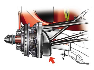
Instead of running vented solid side covers, I wonder if a spoked side cover would work? You would get the maximun open area. Most likely be spendy though...
Before swapping over to the vented hole side plates I wanted to get a better understanding of the effect of the motor RPM on R1, the heat conductivity between the stator and the shell. This will be important for comparing the effectiveness of both internal blades with no holes, and oil filled strategies, as both of these will increase the heat flow from the stator to the shell but don't have any real effect on the ability to dissipate from the shell to ambient.
Here is the raw data at 100, 200, 300, and 400 RPM:

What is interesting is that the temperature rise of the motor core was nearly identical at all speeds, hitting the CA's thermal rollback after 19 minutes. So at first it looks like the RPM has little effect. But, even though the I^2R copper heating is identical in all of them during the first 19 minutes, the faster RPM tests have more eddy/hysteresis losses, and so total heat being dissipated by the hub is greater in those runs, which you can see from the watts in curves
Using the steady state values, it is easy to compute the equivalent R1 term. At 300 RPM for instance, the steady state power is about 205 watts, the stator is 119 degrees, the shell is 63 degrees, so:
1/R1 = 205/(119-63) = 3.66 Watts/degree
Here is the conductivity for R1 from stator to shell, plotted as function of RPM, in the case of a sealed motor with no internal fan blades and no oil:

It would appear from this data that at higher RPMs the motor can sustain more phase current and torque because the abililty to dissipate heat from the stator is improved. After the CA's thermal rollback kicked in and reached steady state, the thermal power input that could be sustained for a 120 degree core in the 400 RPM run was ~222 watts, versus around 175 watts at 100 RPM.
However, that difference (~50 watts) is only slightly more than the additional cogging/hysteresis losses that are also present from the higher RPM, which means that the increase in sustainable phase current at 400 RPM versus 100 RPM is still pretty marginal. Which implies in a nutshell that the steady state torque output capability of the hub motor doesn't improve much at the higher RPMs. What gains there in better internal air turbulance to move the heat around is mostly offset by the additional heat that is generated by the greater motor core losses.
I'm in the process of getting the R1 data at 0, 500, and 600 rpm, but there are complications doing that by the same technique heating them up under load with the dyno so instead I'll heat the motor first and then study the cooling profile while the hub is spinning at those RPM's to get the resistances.
Here is the raw data at 100, 200, 300, and 400 RPM:
What is interesting is that the temperature rise of the motor core was nearly identical at all speeds, hitting the CA's thermal rollback after 19 minutes. So at first it looks like the RPM has little effect. But, even though the I^2R copper heating is identical in all of them during the first 19 minutes, the faster RPM tests have more eddy/hysteresis losses, and so total heat being dissipated by the hub is greater in those runs, which you can see from the watts in curves
Using the steady state values, it is easy to compute the equivalent R1 term. At 300 RPM for instance, the steady state power is about 205 watts, the stator is 119 degrees, the shell is 63 degrees, so:
1/R1 = 205/(119-63) = 3.66 Watts/degree
Here is the conductivity for R1 from stator to shell, plotted as function of RPM, in the case of a sealed motor with no internal fan blades and no oil:
It would appear from this data that at higher RPMs the motor can sustain more phase current and torque because the abililty to dissipate heat from the stator is improved. After the CA's thermal rollback kicked in and reached steady state, the thermal power input that could be sustained for a 120 degree core in the 400 RPM run was ~222 watts, versus around 175 watts at 100 RPM.
However, that difference (~50 watts) is only slightly more than the additional cogging/hysteresis losses that are also present from the higher RPM, which means that the increase in sustainable phase current at 400 RPM versus 100 RPM is still pretty marginal. Which implies in a nutshell that the steady state torque output capability of the hub motor doesn't improve much at the higher RPMs. What gains there in better internal air turbulance to move the heat around is mostly offset by the additional heat that is generated by the greater motor core losses.
I'm in the process of getting the R1 data at 0, 500, and 600 rpm, but there are complications doing that by the same technique heating them up under load with the dyno so instead I'll heat the motor first and then study the cooling profile while the hub is spinning at those RPM's to get the resistances.
Similar threads
- Replies
- 16
- Views
- 305
- Replies
- 63
- Views
- 4,245
- Replies
- 23
- Views
- 3,432
- Replies
- 19
- Views
- 1,756