Delayed overshoot in torque assist after pause in pedalling (Sempu T2 + Cycle Analyst)

Mahe

10 mW
Joined
Sep 13, 2019
Messages
24
Hi,
I have been running a GMAC + Phaserunner + Cycle Analyst (all 3 from Grin) + Sempu T2 torque sensor (Aliexpress) for a few years now and while the overall performance is generally good, I have been frustated with the torque assist. The main issue is a delayed response of the motor after a pause in pedalling, with an overshoot of about 2x the "steady" assist. Note the CA is not 100% compatible with the Sempu since the latter has 48 poles and the CA v3.15 only allows up to 32 poles in the setup, but I was told this only affects the Human Watts reading. Anyway, I finally found the time to investigate what's going on in more details, and I'm hoping to get feedbacks for improvement here.

I used the Grin programming cable to log the CA data onto my laptop . What I found is that there is 1) a tendency of the torque signal to overshoot (sensor only or sensor-CA communication?) 2) a small lag between torque sensing and the generated throttle output (from the CA perspective), but probably more determining is 3) a longer lag between throttle output (or input into the controller) and the ampere reading. Now the graphs make me thing the apparently long lag may be partly an issue in the logging of the Ampere signal, but I might nevertheless have the finger on something. Anyone has knowledge or experience with the response time of the Phaserunner controller to the throttle signal?

MORE DETAILS BELOW

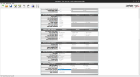
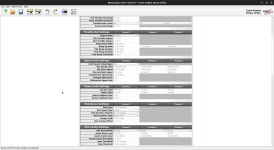
I attached my Phaserunner and CA settings (corresponding to the last run). Note I reduced the throttle ramp up signal to 1 ms.

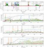
The log data should be 10 Hz, so every 10 steps in the attached graph correspond to 1 second. There are 14 different channels logged out from the CA, but for the sake of usefulness and readability I plotted only RPM (pedal cadence in round per minute, blue, scaled by 1/5), the torque in Nm (orange, scaled by 1/2), the human power as calculated from the previous two (green, scaled by 1/10), the throttle output sent out by the CA to the Phaserunner (red, centered to be zero at rest and scaled by 30), the current in Ampere (drawn from the battery?) (purple, scaled by 10), and the bike Speed (black). The scaling only serves to have it all on the same axes. I used my own calculation for Human watt (essentially RPM * torque) because the Human Watt signal from the CA was significantly lagged, not sure why. Anyway, the most important things are 1) the torque * RPM sigmal received by the CA (green), the throttle output it makes from it (red), and the battery ampere as a result (purple).

I share an overview of 4 "runs" (cut outs to show the same horizontal scale):
1. Pedal torque only. CA averaging over 24 poles, 200 ms Torque Ramp in the phaserunner
2. Pedal torque only. No CA averaging, 200 ms Torque Ramp in the phaserunner
3. Pedal torque only. No CA averaging, 1 ms Torque Ramp in the phaserunner
4. Throttle input then pedal torque. No CA averaging, 1 ms Torque Ramp in the phaserunner

Figure-allruns-aligned.png
and then a zoon on the latest run with:
1. overview
2. input only
3. throttle only
Figure_throttle-delay.png
From the many things one can see from these graphs, I'd like to draw your attention on the following:
- (First Figure): There tend to be a peak in the torque, generally after a break in pedalling (after the blue curve gets to something greater than 0), though it sometimes happens a little later. It might be a true signal, but it suspect it is exxagerated / an amplificatoin. That is likely related to the sensor itself (or how it communicated with the CA)
- (All Figure) there is a small lag, and in any case no 1:1 correspondance, between the RPM*torque signal and the CA throttle output response, which cannot be explained by the ramp-up limit of 4V/sec (the first run had a slower ramp up, but the lag can be observed even in the latest experiments).
- (First Figure): the torque signal shown (orange and green) is after the averaging (the oscillations get much larger from the second panel, after removing CA averaging).
- (All figures): there is an apparent lag of about 10 steps (~1 second) between the throttle input and ampere reading, which I interprete as a lag in the phaserunner.
- (Second figure, second panel): in the second of three throttle only input, I see the speed increases before 5 steps (500ms) before the ampere reading, which suggests an error in the reading. However, the speed signal is obserbed about 10 steps (1 sec) after the throttle signal. Note the throttle rises as a triangle because it is limited to about 2V/second ramp up -- this corresponds to the up slop after correcting for the *30 scaling factor.

When used with the throttle, the lag does not matter much, but it is frustrating when used from torque assist, where you'd expect a much more direct response to the pedalling (especially with such a sensor like the Sempu with many poles). This is especially frustrating when it combines with the torque peak after a pedalling break, leading to a delayed overshoot. In the course of these experiments, removing the CA averaging did improve the felt responsiveness, but removing the 200ms throttle ramp up in the Phaserunner did not.

I feel for improved diagnostic I'd need a more accurate reading of the battery current draw in response to the throttle output from CA, but I'm not sure how best to do this.

Thanks to anyone reading to this point.

Looking forward to feedbacks to understand and improve the issue I am experiencing.
Mahé
 

Attachments

  • phaserunner_basic.png
    phaserunner_basic.png
    226.5 KB · Views: 2
  • cav3_settings.png
    cav3_settings.png
    212.3 KB · Views: 2
Some thoughts below to clarify a few things; I don't know if any of them will directly help fix the issue:


I have been running a GMAC + Phaserunner + Cycle Analyst (all 3 from Grin) + Sempu T2 torque sensor (Aliexpress) for a few years now and while the overall performance is generally good, I have been frustated with the torque assist. The main issue is a delayed response of the motor after a pause in pedalling, with an overshoot of about 2x the "steady" assist. Note the CA is not 100% compatible with the Sempu since the latter has 48 poles and the CA v3.15 only allows up to 32 poles in the setup, but I was told this only affects the Human Watts reading.

The poles is only the cadence sensor, and does not (directly) affect anything to do with torque sensing. It only affects any of the CA settings and readings that use cadence as an input source.

This can include the time to start assisting. The more poles, the faster the CA can respond, because there is less time before however many poles have passed to start the assist. (the CA has settings for that part)


I used the Grin programming cable to log the CA data onto my laptop . What I found is that there is 1) a tendency of the torque signal to overshoot (sensor only or sensor-CA communication?)
There is no communication*** between sensors and the CA, or the CA and anything (except via that programming serial cable on that TRS connector).

The torque sensor simply outputs a voltage on the TS signal wire, and the CA converts that voltage into data it uses internally.

The cadence sensor on the TS unit outputs one digital signal that indicates speed of sensor rotation, and some of them also output another digital signal that indicates direction. The CA reads these the same way it does brake lever inputs, etc., as just on/off pulses that it counts for cadence, and as forward or reverse direction of pedalling.

***communication implies a data stream of some sort, most commonly a digital serial data line with a specific data format and protocol; the CA doesn't use this for any of it's normal operations between it and any sensors or controller, etc.


- (All figures): there is an apparent lag of about 10 steps (~1 second) between the throttle input and ampere reading, which I interprete as a lag in the phaserunner.
Assuming this is a real lag, then: If you have a whole second between throttle input and motor start (or change in motor operation, causing change in battery current) in the PR, you need to tune the PR so it has no delay to throttle response.

If there really is a whole second's lag like that, you'd feel it, for instance from a stop it would take an entire second before the PR responded to any throttle input (regardless of source).

I have what feels like zero delay on mine (but haven't logged it to see the actual time response). It's certainly not anywhere near a second if there is any delay at all, via either throttle or cadence control (I don't use the torque sensor part of my Thun, on the SB Cruiser trike, just the cadence sensor that hte CAv3 converts to a throttle signal).

My PRv6 is using default settings for all timing related options, AFAICR. I don't think I've experimented with those yet.


- (Second figure, second panel): in the second of three throttle only input, I see the speed increases before 5 steps (500ms) before the ampere reading, which suggests an error in the reading. However, the speed signal is obserbed about 10 steps (1 sec) after the throttle signal. Note the throttle rises as a triangle because it is limited to about 2V/second ramp up -- this corresponds to the up slop after correcting for the *30 scaling factor.
This sounds like either the logged data is being sent out of time sequence from the CA, or the display program is incorrectly or inconsistently displaying the data sequence. If it's the former, then you can't directly tell looking at the log, but the latter you can see by looking at the logged data vs time to see which data sets / pairs actually come together from the CA.


In the course of these experiments, removing the CA averaging did improve the felt responsiveness, but removing the 200ms throttle ramp up in the Phaserunner did not.

What happens if you directly connect the torque sensor to the PR and configure the PR to respond direclty to it, disconnecting the CA's throttle input entirely? (this would eliminate all delays / etc caused by any CA functions).

At least some Sempus have a torque output that approximately corresponds to a throttle voltage range, so if you need to you can configure the PR's throttle input voltage range to match what you actually see on the Sempu, and use it as a "pedal throttle". This method skips the cadence sensor entirely, and would have no delays other than whatever delay the PR itself has to it's own throttle input.

Alternately you can use the TS and cadence inputs on the PR to do it if yours has one, and then tune the PR similarly to how you have tuned the CA to see how it's response works out.
PAS_Cable_Pinout.png
PAS Connector: A 6 pin HiGo plug provides an input for the direct hookup of either PAS or Torque sensors to the motor controller. This is required for pedalec ebikes that don't use a Cycle Analyst. With a Cycle Analyst system this plug is not used as the PAS sensors, throttles, and all accessories plug into the CA3 instead.


I feel for improved diagnostic I'd need a more accurate reading of the battery current draw in response to the throttle output from CA, but I'm not sure how best to do this.
Not sure what you mean; the CA itself already does this if you have it wired up to a shunt in your battery circuit, or to the controller's shunt, and is correctly calibrated for that shunt. I haven't used the logging feature to see it together with throttle output but it should be accurate there as it's the same data the CA is actually using for it's calculations.
 

Attachments

  • 1704044312483.png
    1704044312483.png
    41 KB · Views: 1
Hi @amberwolf ,
first of all thank you very much for the prompt and thorough reply. I'll try to be as thorough in mine.
There is no communication*** between sensors and the CA, or the CA and anything (except via that programming serial cable on that TRS connector).
***communication implies a data stream of some sort, most commonly a digital serial data line with a specific data format and protocol; the CA doesn't use this for any of it's normal operations between it and any sensors or controller, etc.
I intended it more in a psychological sense, including some of the processing to make sense of the perceived signal. In the RPM case, that would be the counting of the pulses. But true, the torque is more straightforward, so it is unlikely, besides possible averaging issues. That leaves the sensor as sole responsible for the pulse. I do have a replacement sensor which I can try -- that will require a little work so I am not sure when I can test that.
Assuming this is a real lag, then: If you have a whole second between throttle input and motor start (or change in motor operation, causing change in battery current) in the PR, you need to tune the PR so it has no delay to throttle response.
How can I tune it besides adjusting the throttle ramp up parameter ? (which I did)
If there really is a whole second's lag like that, you'd feel it, for instance from a stop it would take an entire second before the PR responded to any throttle input (regardless of source).
Yeah, one second is really a lot. It really looks like a logging issue. I also noted a similar, 1Hz output for the native Human Watt output signal from the CA. Possibly the logging might be buggy for some signals.
This sounds like either the logged data is being sent out of time sequence from the CA, or the display program is incorrectly or inconsistently displaying the data sequence. If it's the former, then you can't directly tell looking at the log
For plotting I simply read the output CSV file in python -- pandas dataframe, all on a common axis, so I don't expect any bug there, unless the CSV file is corrupt in the first place, i.e. issue during aquisition. What do you mean, I can just tell by looking at the LOG? At such high frequency it's hard to see anything really.
I feel for improved diagnostic I'd need a more accurate reading of the battery current draw in response to the throttle output from CA, but I'm not sure how best to do this.
Not sure what you mean; the CA itself already does this if you have it wired up to a shunt in your battery circuit, or to the controller's shunt, and is correctly calibrated for that shunt. I haven't used the logging feature to see it together with throttle output but it should be accurate there as it's the same data the CA is actually using for it's calculations.
I mean I would need a true measure of the current draw (from the battery or into the motor, regardless) to double check versus throttle input. I can of course do it with a multimeter, or any other device, but I loose the common axis of time from the CA logs, which is essential to detect the leads and lags. I'd need to hookup on the throttle in signal and on the battery current, and log both signals for later analysis. This is possible but more involved than just acquiring the CA output log through a serial USB. Or do you say I could use the CA to do just that? Which output would that be in the log then? (the log is made of 14 columns with pre-specified variables, i cannot choose what comes out).
Alernatively, I could simply measure the bike speed in response to the throttle, with a weakly loaded bike, and after removing any limitation on the CA throttle ramp up. The beginning of acceleration would mark the start.


Alternately you can use the TS and cadence inputs on the PR to do it if yours has one, and then tune the PR similarly to how you have tuned the CA to see how it's response works out.
I have a PRv2 I believe, which does not have the PAS sensor. I'll double check the torque voltage signal and see if I can plug that in -- thanks for the suggestion (I remember reading something like this long ago but did not think about it anymore).

Anyway, from my side, TODO:
1. further check on possible PR lag versus logging issue:
- use unloaded speed as a proxy, check lag in response to throttle, remove any limit on CA throttle rampup
2. check if possible to plug the torque sensor directly as throttle input (that will take some time)
3. try a replacement sensor (that will take some time)

Again, many thanks for your input.
 
A thought that might not be applicable, but:
they were losing data from the stream at faster rates. I'm not sure that this could cause any of the issues you see in the logged data, and it wouldnt' have anything to do with the real problem, though.

Not sure if this would be helpful, but found it while looking up other things
"Log output file is CSV with CA, Phaserunner and GPS Data per line"
so it could also log the PR's serial data stream if yours supports that; the PR monitors it's own battery current (and phase current) and throttle input, so you could use this data to verify timing is correct in what you're seeing in the CA data.

There are also simple and tiny serial-data-logger hardware boards so you can log data while riding without carrying much in the way of extra hardware, if you aren't already using them, like the ones in my post here:
I have no experience with them, but they seem like they'd be easy to use, and do more or less what the Cycle Analogger does (which I *have* used and is literally plug and play).
 
Hi @amberwolf, thanks for the hints. As far as I understand, some of the tools you cite use the TTL output from the CA, which I also used for data acquisition. I used a pretty tried and tested tool (putty) for the serial USB reading so I wouldn't expext any issue there. To me this points to an issue internal to the CA for amperes and for the Human Watt (not shown) channels, which have a lesser sampling rate.

so it could also log the PR's serial data stream if yours supports that; the PR monitors it's own battery current (and phase current) and throttle input, so you could use this data to verify timing is correct in what you're seeing in the CA data
Sensing from the PR simultaneously would be the right thing to do indeed. I need to purchase another TTL cable.
 
If there's any way for you to hook up just your physical throttle to your PR's throttle input, and disconnect the CA, to verify if the problem does or does not happen without the CA. You'll have to be sure to change the PR's response voltage range to match the actual throttle.

If it happens without it, then you can skip any messing with the CA, and just work on the PR settings.

It it does not happen anymore, then you know the problem is something in the CA settings and work on just those.

It should save much more time and frustration than it will engender by having to temporarily rewire things, and is much faster to do than swapping out the BB sensor unit. :)


Theoretically just setting the CA to BYPASS (I think PASS THRU still modifies voltage range) mode does the same thing, but if it doesn't change things, I'd still physically try the direct throttle connection.


Also, if you haven't already, you could try changing all the CA ramping values in any place it has them to 99v/s. I have always used them that way, so it has as close to zero delay as possible to any input I make.

How can I tune it besides adjusting the throttle ramp up parameter ? (which I did)
I'm not sure; I haven't done any tuning of mine yet. :oops: (hasn't been the need so far).

It might have to do with the PID loop tuning for the motor response itself; I have not had issues with my usage and that so have not messed with this, since it is not an easy thing to get right based on other threads I've read around here and their problems and results. (I try not to actually obey my motto of "if it's not broken, fix it till it is" :lol: )


Yeah, one second is really a lot. It really looks like a logging issue. I also noted a similar, 1Hz output for the native Human Watt output signal from the CA. Possibly the logging might be buggy for some signals.
That's what it sounds like--some parameters may not be stored as often as others to be sent out to the serial port. Been trying to look that up, so far just found the stuff in the previous post just above this one.


What do you mean, I can just tell by looking at the LOG? At such high frequency it's hard to see anything really.
I actually said you *can't* tell ;) ...at least for whether data is out of sequence, since you can't know that the data was sent in the right order. :(

Theoretically you could tell if the data in the log was displayed out of order by the display program, by looking at the values for a particular graph line in the log file and comparing to the graph line itself...but it is pretty unlikely that one graph line would be off but others created at the same time from the same "line" of log data wouldn't be as well.


BTW, there is a note in the CA manual
"The transmitted values are the sameaveraged data that is presented on the CA's display screen. When using the fast10Hz log rate, it is recommended to set the Display Averaging parameter to 0.08seconds so that each logged data value is unique and not repeated"
so if you haven't got the display set to show values fast enough then the log won't show them either.


I mean I would need a true measure of the current draw (from the battery or into the motor, regardless) to double check versus throttle input. I can of course do it with a multimeter, or any other device, but I loose the common axis of time from the CA logs, which is essential to detect the leads and lags. I'd need to hookup on the throttle in signal and on the battery current, and log both signals for later analysis. This is possible but more involved than just acquiring the CA output log through a serial USB. Or do you say I could use the CA to do just that? Which output would that be in the log then? (the log is made of 14 columns with pre-specified variables, i cannot choose what comes out).
The log includes A (battery amps) and ThO (throttle output from the CA), which should be identical to whatever actually goes into the PR's battery input and throttle input.

There is also the ThI (throttle input to the CA) but it's only useful for your physical throttle's output voltage going into the CA.

There isn't a logged signal for the torque sensor voltage itself, just the following:

Ah V(oltage) A(mps) S(peed) D(istance) Deg(rees) RPM(cadence) HW(humanwatts) Nm(torquesensor translation) ThI(throttleinput) ThO(throttleouptut) AuxA AuxD Flgs(limit flags)

(if it wouldn't hurt anything electrically (shouldn't?), and you could disable any usage of the AuxA port for the CA to do any limiting/preset-control/etc with, you could parallel connect the torque sensor input to the AuxA input and thus use it as a logging port for the torque sensor's actual voltage)

BTW, are any of the CA limit flags capitalizing when the problem happens? (these are logged, too, in case you miss them on screen)

Alernatively, I could simply measure the bike speed in response to the throttle, with a weakly loaded bike, and after removing any limitation on the CA throttle ramp up. The beginning of acceleration would mark the start.

Those signals are all logged in the CA stream, so you can analyze using that, if you have to do it that way. (I don't know how to do the analysis, though, me and math are not friends).


I have a PRv2 I believe, which does not have the PAS sensor. I'll double check the torque voltage signal and see if I can plug that in -- thanks for the suggestion (I remember reading something like this long ago but did not think about it anymore).

Ah. I use the PRv6, but just got a slighly used PRv1 (I think); not yet worked with (just powered up and verified it can talk with the PRSS over serial). it doens't have the PAS / torque input either...the v6 does but I haven't played with it yet.
 
"The transmitted values are the sameaveraged data that is presented on the CA's display screen. When using the fast10Hz log rate, it is recommended to set the Display Averaging parameter to 0.08seconds so that each logged data value is unique and not repeated"
Wow, I had overseen this. I just noticed the corresponding menu in the CA. I even set it to 0.04. And bingo, gone with the averaging. And gone the delay between throttle output signal and PR current (and bike speed). The figure below shows the unloaded bike response to throttle input: throttle Out, battery current (A) and (unloaded) speed.
1704137583403.png
I'll make real-world experiments soon to focus on the original matter: response to the torque sensor.
Thanks, that was useful.
 
Hi again,
I took some more data from a short trip today -- this time I use my phone with an Android app: "Serial USB Terminal" for convenience, which also nicely provides a time stamp. That way I could plot the figure with the x axis representing the time in seconds. I also attached a screenshot of my CA configuration. I use a setting with either low (HW x 0.25), medium (HW x 1), or high (HW x 2) assistance, where HW is the human Watt input, which in my case is double the true input (due to setting to 1 rev = 24 poles instead of 48), and assuming the torque sensor calibration is correct (+-20% ?). Note in these experiments the assist threshold is HW = 40 Watt. In the area of interest below, I must be in "low" assistance.
rosa_and_back.png
The first panel shows the overall trip, and the second panel is a zoom out of the grey area, where I made repeated tests of stopping and restarting pedalling. That was on a slight downslope where the bike would keep going despite stopping to pedal, and no significant force was needed to restart pedalling. In most cases I left the feet on the pedals (so the orange torque line is more than 0). In a few cases (3rd and 4th restarts) I intentionally rose the feet to apply virtually zero weight on the pedals, so the the human watt is less than the assist threshold (40W here). The figure clearly s hows the overshoot in battery current (purple line), related to an overshoot in the Thorque Out signal (red line), in all but the "no feet" breaks (3rd and 4th). In the 5th and 6th restarts, the power overshoot is clearly related to a strong HW overshoot (green), itself due to a torque overshoot (orange).
Surprisingly, the torque overshoot is not clearly visible from the 1st and 2nd restarts. Is there a possibility that it might have been present at higher than 10Hz, and thus lost in the CA output sampling?

Anyway, this new set of experiments rules out any issue with the PR controller (ThOut and Ampere are tightly related).
Instead, what seems to happen is that a pause in pedalling with some weight on the pedals, followed by a restart, results in a peak in the torque signal. So it looks like an issue with the Sempu T2 sensor, but I cannot rule out, and I even tend to suspect, an issue with the CA, possibly related to averaging (a bug?). I'd need an independent reading on the torque sensor to sort this out.

EDIT: I added the RPM in full scale and highlighted the 68 RPM cadence limit (here scaled x2 to align with the CA setting of max 24 poles, which yields to RPM and HW scaled by 2) that the CA 18 ms loop cycle can handle properly. I quote an email from Justin One problem with a 48 pole sensor though is that once your cadence exceeds 68 rpm (the speed at which you occasionally get two PAS interupts within a single 18mS loop cycle) the spacial averaging will increasingly deviate, so at say 100 rpm it would be averaging over 0.75 of a crank rotation instead of 0.5 crank rotations and you may start to notice some aliasing of the pedal torque to motor torque. However this is high enough so that it does not seem to interfere in the experments.
I also got the hint to update the CA firmware I would also recommend using the CA3.2B3 firmware rather than 3.15 since that has the option for torque assist off the line before any PAS signals are detected. See [URL]https://www.youtube.com/watch?v=6v-_HECwBAQ[/URL]. I'll report here on any progress.
 

Attachments

  • serial_20240103_161500.txt
    1.4 MB · Views: 0
  • CAsetting.png
    CAsetting.png
    208.2 KB · Views: 2
Last edited:
Follow-up. I made another trying using the latest CAv3-2b3 firmware. Unfortunately it did not improve things. Actually it felt more of a kick-start + overshoot than the CAv3-1.5 version. There was even a strange instance of start-and-stop in motor assistance (first half of Zoom 2 and start of Zoom 3), which I had not experienced before and definitely felt buggy. These occured in an area where the torque signal was even more peaky than usual. This apparent worsening -- dependence - of the torque signal upon software versions does point to a software issue rather than a sensor issue, but i cannot exclude chance (I'd had to post 10s such messages with a more standardized track / behavior, would that be any useful?). In the meanwhile I switched back to 1.5 version. Note that in the 2b3 version the torque signal is not averaged any more in the logged output (orange, and as a result the computed HW as RPM*torque, continuous green line). The HW output is (green dashed line ).
 

Attachments

  • CAv3-2b3.png
    CAv3-2b3.png
    1.4 MB · Views: 2
Back
Top