DIY electric Drift trike - After some advice with error code 8/9 please sw900. Any input greatly appreciated!!!

TheWelshGuy

100 µW
Joined
Jun 5, 2023
Messages
7
Location
Wrexham
Hi Folks, new member here...
20230529_175010.jpg

Recently finished building an E-Drift trike but on 3rd good ride out I've thrown some error codes and just wanted some advice. Already done some research but I've not got any of the common symptoms others are mentioning.

Worth noting that I'm a relative novice when it comes to electrics too so please bear with me.

Specs are:
Golden Motor pro 901 hub 1000w (will take up to 1700w apparently)
48v 20.4ah battery
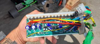
1500w dcmoto controller
Sw900 display
Thumb throttle.

When I first got it put together it was throwing error 8 (throttle) connector was loose on fem side so took to bits, re shaped everything so it goes together nice and snug - problem sorted. Been perfect since.

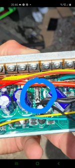
Yesterday after a bit of a ride on the drift wheels (lots of vibration from them) it suddenly stopped responding and threw error 8, figured no biggie, pulled the lid off the enclosure and fiddled about with connector and now my error code seems to alternate between 8 and 9.

Seems like most error 9's online act like a shorted phase wire and prevent the hub turning freely or causing resistance... I've got none of that, hub turns freely, heard no pops, nothing got hot etc etc...

Obvs error 9 is listed as communication error between controller and display, could that be triggered by an error 8 problem? - I.e- loss of signal from throttle etc?

Just seems strange that its alternating between 2 codes.
It seems to favour 9 at the minute, but if I fiddle with throttle connector it switches to 8, fiddle again, back to 9 etc etc.

At a bit of a loss where to go from here in terms if testing process, or even how to test to be truthful.
I do have access to a multi meter although I wouldn't know how to use it on an e bike controller.

Thanks in advance.

Tom
 
Upon further investigation it would appear that I have a short on yellow phase and that the wheel was in fact cogging, not sure how I missed that yesterday... unplug yellow phase, wheel turns freely. Plugged in it cogs motor. Blue and green are fine.

So I assume it's one of the mosfets...
Second question, any ideas how to identify which FET is the culprit? Watched several videos but I'm getting all kinds of readings when following instructions. My multimeter model also doesnt beep to signal so I'm relying on what I see on screen only... none of which seems to make any sense to me.
Obviously I've got the controller in bits now and there is no obvious visible damage, solder looks solid etc etc
 
I’m afraid I can’t help with most of your questions, but your error 9 / communication problem could just be a plug issue. My own ebike will have a similar error with the KT controller from time to time because the pins in the JST-type plug aren’t mating well. Waterproof style connectors seem to be of higher quality, make better connections and are less prone to rattle out of place. Check your connections, wiggle the plugs, check the wires heading into the plug, etc.
 
I’m afraid I can’t help with most of your questions, but your error 9 / communication problem could just be a plug issue. My own ebike will have a similar error with the KT controller from time to time because the pins in the JST-type plug aren’t mating well. Waterproof style connectors seem to be of higher quality, make better connections and are less prone to rattle out of place. Check your connections, wiggle the plugs, check the wires heading into the plug, etc.
Yea I've managed to isolate the error 8 (throttle) to bad connection... however the error 9 seems to be permanent. Checked all wires/ connections etc.

With the new discovery of motor resistance when yellow phase is plugged in it leads me to think it is one of the mosfets, now if I can just identify which one I can maybe source a replacement.
Best of luck!

That’s out of my arena. I fix non-functional controllers by replacing them. Bless the people who are more electronics literate than I am.
 
Best of luck!

That’s out of my arena. I fix non-functional controllers by replacing them. Bless the people who are more electronics literate than I am.
To be honest that's probably the best bet for what they cost... my major concern was what made it die to begin with tbh and will it happen again.


Thanks for your input none the less
 
What exactly are your multimeter settings, lead connections for each test, and readings for each test? This may help us tell you what your readings mean.

Regarding repair: Blown FETs sometimes also blow their gate drivers, depending on the cause of the FET failure. So if you replace the failed FETs with the same part number, get readings the same between all phases, and it still doesn't work, it could be gate drivers failed either stuck on or blown open, or the gate resistor burned open.

Because of that it's usually easier / cheaper to replace the controller, as long as you know the cause was not something external to it (if it was, fix that first, and if it was conditions causing it, change the conditions to reduce controller stress, or replace with one that can handle those conditions).


Regarding cause: the most common cause of FET failure is just cheap controller design and manufacturing with little or no QC, when there is no physical damage to the motor cabling or motor itself. Mostly this is because these only measure battery current, not phase (FET) current, so have no way to know what is happening to the FETs at any instant, and overloading them is easy to do.

Cable damage is usually at the axle exit of the motor, and usually caused by impact of the axle end on something, most commonly the ground when laying down the bike (on purpose or accidentally), sometimes in the shipping box for the motor/kit there's little protection for the axle end and it gets banged on things thru a hole in the box.

Overloading a cheaply-designed controller by running it at it's max a lot can also do it, especially if it is in a poorly ventilated location so it doesn't shed the heat it generates.

Hitting stall current (very slow or locked rotor) at high throttle for long enough can also do it, with any of the many controllers that don't measure phase current.


THe error numbers probably "toggle" becuase of programming priority--the error tree likely starts with the smallest number, so it only shows the first error of however many there are. When you make the first error go away, the next one shows up, and so on.

Technical stuff in manuals is often poorly translated, so error codes and the like may not actually mean exactly what they say. Worse, one translation may be based on a previous bad one, but reworded by someone else that doesn't know anything about the technical stuff either, and made less meaningful. So whether the results you see match what they say they mean depends on the translation abilities of everyone that worked on that manual (or any other references you use).

It also depends on whether the person taht wrote the firmware version of the display you're using used the error code number provided by the other person that wrote the firwmare version of the controller youre using for any particular error it detects...because they may not actually match. :/

And...whether the manual the error code info comes from was written by someone that talked to the person that wrote that display firmware version.... Etc.
 
Last edited:
Sorry for the late reply, I've been flat out on work.

Unable to provide data at the moment but after a second review with a calmer head I'm pretty sure I have a short on neg green phase and pos yellow phase.

I suspect I may have found the reason I have blown FETs/gates....
I opened the case out of curiosity and I've found what I believe is a "heavy shunt mod" on the rails.

Is this likely to be what's caused current overload and killed something?
 

Attachments

  • 20230605_121753.jpg
    20230605_121753.jpg
    1.8 MB · Views: 6
  • Screenshot_20230607-204610_Messenger.jpg
    Screenshot_20230607-204610_Messenger.jpg
    548.3 KB · Views: 4
Get some solder wick (copper color) and take the added shunt solder off and see what happen, you could be right in that it friend something. Remember to look on the bottom side for a quick visual check, but for the topside you can see if the caps have puffed out.
 
That could certainly do it. A mod like that essentially turns the shunt into a piece of wire, so the controller has no idea how much current is actually flowing, and cannot protect itself.

YOu might be able to remove all the solder/etc from the manganin shunts, but they will still be lower resistance than they started out as, as you'll probably never get all of it off, so the controller will still be being "lied to" about the current, and won't react to overcurrents as well as it should (because it doesn't think they are overcurrents)...it won't be nearly as bad as it is now, but it could still cause failures if it's high enough, depending on the controller hardware and software design and parts actually used in it.
 
To be fair, I only paid 40 for the controller, display and throttle so for the money I have in it I might as well just buy a new one and keep this for any other spare parts that can potentially be pilfered from it or an eventual repair etc.

At least I know that was likely the cause so hopefully it will be an isolated issue and wont happen with a brand new un modded 1500w controller.

Thanks Gents
 
I'd go for the controller that does not need a display, and a controller that can be used sensored or sensorless.
Indeed the wimpier the power levels the cheaper the controller, but even a 1250w or 48v 25a is pretty cheap, plus its good to have that as a spare if you dabble in display. Displays just add to much complexity, I mean all those dumb wires, not needed IMHO. Plus a display just adds more junk to your handlebar, and more eye-candy for passerby's to eye your ride, which is just uneeded attention. Best to fly under the radar, lay low, go slow.
 
I prefer to have a display to be honest, I can check wattage pulled, exact battery voltage, range travelled, top speed, average speed etc etc.
Not to mention the setup aspect, safe voltage cutoff.. max amps/speed etc all controlled from a neat little screen.
 
Back
Top