Dual Freewheel Front Sprocket system

jdcburg

100 W
Joined
Aug 3, 2009
Messages
175
Location
massachusetts usa
Hello folks - I have developed and bench tested a prototype dual freewheel front sprocket system to allow an emotor to power the bicycle through the pedal crank so the shifting system (rear hub or derailleur) can be utilized. One freewheel allows the cranks to remain stationary when under motor power (nothing new there) and the second freewheel allows the motor driven sprocket (on the BB spindle) to remain stationary when under pedal power, reducing drag caused by the motor system to a minimum. I've posted a video on YouTube of the rough first prototype during a bench test. I'll try to link to it below. If others are interested I'll post details. - jd

[youtube]uPVs_g9xseE[/youtube]

(Fixed link - Thanks Tyler)
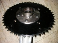
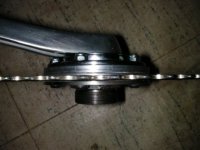
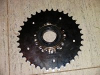
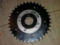
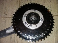
 
Fixed the youpube link.
[youtube]uPVs_g9xseE[/youtube]
 
I think I've fixed it in the original post now. Thank you - jd
 
jdcburg said:
Hello folks - I have developed and bench tested a prototype dual freewheel front sprocket system to allow an emotor to power the bicycle through the pedal crank so the shifting system (rear hub or derailleur) can be utilized.

Cool design! Similar to the Sun IPS system but with one additional freewheel.
 
Nice use of the front freewheel system! I did something similar but am using a two stage jackshaft instead of a single reduction drive. I bet your mechanical losses are lower. Anyways you can check it out a ways down the non-hub motor drive section. "HIV Improvements" or something like that. I can't remember the title exactly...
 
That’s a nice build dequinox. Much cleaner than mine. I don’t need the external 2-stage reduction because the Unite MY1016Z3 comes with a built-in 9.87:1 gearbox. But I wanted the FW down on the BB spindle to cut losses as much as possible. The downside is wider crank spacing/ Q angle. I haven’t tried epower on the road because I haven’t mounted the batteries yet but I took it out for a pedal. It’s different but not uncomfortable. I think I’ll want a chainguard or be sure to tie my pants in to avoid clothing-in-the-chain syndrome.

The design requires the pedal sprocket to be to be the final drive sprocket, and it must be the lateral one (closest to the right crank). Both freewheels work independently to engage that sprocket – the crank from the right side and the motor driven sprocket from the left side. The motor sprocket freewheel is an ACS Southpaw BMX sprocket with 1.37” x 24 tpi LH threads. I had an adapter consisting of a flange welded to a right BB cup fabricated. The right BB cup has LH threads to match the Southpaw (thanks to someone from a post here last fall). The adapter is bolted to the midline side of the pedal sprocket. I bolted a 36T sprocket to the Southpaw sprocket. When engaged, the freewheel tightens onto the adapter, so no thread dope is needed. I got the sprockets, flanged freewheel and cranks from SickBikeParts and the 159 mm BB spindle from Cyclone. The Southpaw is widely available. I had a few other parts fabricated: some spacers and a backing ring for bolting the 36T to the Southpaw. SBP has sprockets available from 24T to 48T, but I figured the 36T motor and 44T pedal were about right. The 8-speed rear cassette is 11-33.

I’ve attached a few images below of various parts. I’ll keep you posted of further developments. I definitely need the fabricated adapter redone because the excessive runout is causing wobble of the motor sprocket, visible in the video. - jd
 

Attachments

  • dfw01a.JPG
    20.3 KB · Views: 5,936
  • dfw02a.JPG
    dfw02a.JPG
    27.4 KB · Views: 18,396
  • dfw04a.JPG
    dfw04a.JPG
    25.9 KB · Views: 18,346
  • dfw05a.JPG
    dfw05a.JPG
    31.2 KB · Views: 18,394
  • dfw06a.JPG
    dfw06a.JPG
    29.9 KB · Views: 18,347
  • dfw11a.JPG
    dfw11a.JPG
    31 KB · Views: 18,353
  • dfw12a.JPG
    21.6 KB · Views: 5,937
OH! I didn't realize you had the dual freewheels both mounted on the BB spindle! Nice job! It loos really clean, esp. for a custom fab job. I probably could have saved some money on my build by spending more time fabricating my own parts...but I wanted stuff to just go together nicely. My build works pretty well, but has a few drawbacks like the "clothing vacuum" that you mentioned!

Anyways I like the idea of the dual freewheel on the crank...I'm sure it's a bit wider but mine is too and I've found that it's ok.

I'll keep looking in to see your progress.
 
I finished her up this week, mounting the batteries and controller and took the first test run today. It was a short run, about 2 miles out and return with some flats and moderate hills. The test went off without any problems. I ran through the gears under pedal power, motor power and blended power. Actually I backed off on the throttle and shifted under pedal power only but I did test the motor in all gears and everything seemed fine. The ratios are just about right - I didn't have a stopwatch but it seemed that about 75-80 cadence topped out the motor rpms. The steepest hill was a breeze to pedal up in 3rd (of 8 speeds). I pedal-assisted on the hills and only pedaled through the gear changes on the flats. The only thing I noticed was when I let her lug down at one point there was a vibration in the motor drive line that was visible by the spring loaded chain tensioner seeming to bounce a little. I just pedaled a bit more and backed off on the throttle and it stopped. It was a test move, not something I would do in normal riding. I hope to borrow a GPS and get some speed data. Also I'll time the cadence more accurately. 10-4 over and out for now - jd
 
Just one more quick note - I used the bicycle analyzer at http://www.arachnoid.com/bike/ to calculate my speeds. If I am correct about the motor powering the pedal sprocket to a cadence of 80 at full motor rpms I should be going 8.3 mph in 1st and 24.8 in 8th. If I changed the pedal sprocket from 44T to 48T, it would change the range from 9 mph to 27 mph, with a corresponding loss of torque. Using the 48T pedal sprocket and changing the motor-driven sprocket from 36T to 24T would increase the cadence to 120 and the top speed to 40.5 mph. My little 350W Unite motor wouldn't do it but you guys with RC motors could easily do that if the rest of the drivetrain could take it - jd
 
Hi TMV - It's a brushed motor with a built-in gear reduction unit of about 10:1. It sounds like an electric drill. The freewheels click like typical freewheels - jd
 
Nice design jdc :) here's my take (as yet untested) at the design. Here are the bits all lined up -
Picture007-1.jpg

Left to right, SBP White Eno with spacer ring, freewheel adaptor, GGoodrum 3-speed freewheel adaptor, SBP White Eno, Eclipse 153mm BB (reversed), Onza T-Pro pedal minus the threaded collar and slightly thinned.
Here it is assembled, with a SBP 36t sprocket with the spacer ring in the middle -
Picture003-1.jpg

On the bike with a Extron kevlar 92T #219 sprocket and adapter -
Picture001.jpg

Picture012.jpg


The pedal drives the BB which in turn connects to the first freewheel adaptor. The reason for going this way was so the freewheel closest to the frame takes the pedalling sprocket and I can achieve a straight chain line.

The second reason for this setup is so the chain is not backdriven, and I can achieve a 10:92 reduction in one step without the problems Deec had back driving a small primary gear and freewheel.

Brian
 
Briangv99- That is an exceptional job you've done. That should make for a very nice, light, powerful, compact E-bike.

:Thumbs up!:


-Luke
 
jdcburg said:
Just one more quick note - I used the bicycle analyzer at http://www.arachnoid.com/bike/ to calculate my speeds. If I am correct about the motor powering the pedal sprocket to a cadence of 80 at full motor rpms I should be going 8.3 mph in 1st and 24.8 in 8th. If I changed the pedal sprocket from 44T to 48T, it would change the range from 9 mph to 27 mph, with a corresponding loss of torque. Using the 48T pedal sprocket and changing the motor-driven sprocket from 36T to 24T would increase the cadence to 120 and the top speed to 40.5 mph. My little 350W Unite motor wouldn't do it but you guys with RC motors could easily do that if the rest of the drivetrain could take it - jd

video :)

if you pedal like crazy you can do it. i have less power and am not very fit and I got mine up there. Mine required a cadence of about 180.
 
Is that your RC reduction drive there?

Do you have any more pics of the other side?

Looks awesome, very compact and minimal, but strong looking.
 
liveforphysics said:
Briangv99- That is an exceptional job you've done. That should make for a very nice, light, powerful, compact E-bike.

:Thumbs up!:


-Luke

cheers Luke, is tough to find enough time to get all the projects together, but will have this one running soon.
veloman said:
Is that your RC reduction drive there?

Do you have any more pics of the other side?

Looks awesome, very compact and minimal, but strong looking.
hi Velo, yep that is Matt's RC drive and frame clamps. Can take more pics on the other side, haven't fitted the 1st stage reduction though. It'll be a #25 chain with 13:66. Trying to pull down the RPM at 44v nominal to something close to pedalling speed in two reduction steps. Hope it works as good as it looks :)
 
briangv99 said:
On the bike with a Extron kevlar 92T #219 sprocket and adapter -
Picture001.jpg

Where did you get the adapter? That's been killing me on my cyclone kit- trying to find a way to put different chainrings in the front with the funky 5 bolt setup that it comes with stock.
 
Brian - That looks really good. I couldn't figure out how to get the cranks and motor independent of each other without having the main chain back to the derailleur be on the outboard chainring. That's because I left the crank freewheel attached to the right crank. The width requires an alignment roller on my system for the lower gears. If I understand your system both freewheels attach to the BB spindle? - jd

ps have you tried it yet, either on the bench or in real life?
 
briangv99 said:
I made the adaptor using 5mm aluminium sheet. All you really need is a jigsaw, drill and a couple holesaws to whip one up :)
And a saucepan from the thriftstore for the aluminum. ;)
 
jdcburg said:
If I understand your system both freewheels attach to the BB spindle? - jd

Hi jd, yes that's right, the crank arm transfers pedal power via the BB spindle, then through the modified MS FW adaptor to the FW closest to the BB shell.

jdcburg said:
ps have you tried it yet, either on the bench or in real life?

haven't been able to put much time into setting it up lately, I've only spun up the pedals by hand and it works fine. The test will be if the set screws in the FW adaptor can transfer the pedal torque to the pedalling FW. Will post up the results soon.

AW - yeah a saucepan would do nicely, but if you've got a metal supplier nearby you can pick up some cheap aluminium off the scrap pile
 
I know it has been a while since you posted your info on the dual freewheel system for a motorized bike, but please contact me about this. I have been looking everywhere for some help with this issue. Trying to put together an electric bike, but can't find a way to keep both pedalling and motor features simultaneously -- every way I try, I end up having to give up one or the other.

Please contact at orsleepr@yahoo.com

Thank you
 
Since it's your first post, you might not have thought about it this way, but:

Rather than private email help that *might* benefit one person, you should start a build thread for your bike, or at the least a question thread about this specific problem, including the things you have already tried, with pictures and/or diagrams, so that all of us can help you, and so that all the questions and answers will be shared with anyone that might come upon this in future (as in this thread you yourself have seen, and other threads on this board discussing things like what you are asking about).

Or you could just peruse the various threads like this, which discuss and sometimes demonstrate various solutions to the problem. There are some relatively easy ones that use off-the-shelf stuff, and some that require custom parts to be manufactured.
 
Yes my design will do what you want. There are also several kits out there that do similar things, although the motor freewheel is generally on the motor so you end up turning the motor chain when you pedal. Only slightly less efficient. Depending on where you live you might consider Cyclone, Elation or Eclipse. I put mine together from parts mostly from SickBikeParts.com. The main thing to consider is a way to get the final drive rpms down to 90-120 if you want to drive through the front chainring and be able to pedal along. That usually involves a 2-stage reduction - jd
 
Back
Top