Dynapack battery BMS wake up? Motocompacto battery dead

Joined
Jan 20, 2023
Messages
22
Location
Wichita, KS
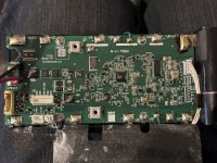
Hey guys. I have been working on adding a range extender in the form of a parallel battery on my Honda Motocompacto and goofed up and hooked it up in parallel without a balancer/balancing like an idiot. After a powercycle or two the internal battery in the Honda stopped outputting any voltage. Took it apart and I'm getting 38.12v across VG/VP but 0v out of the BMS itself. Nothing looks burned, I'm assuming the external battery just tried to pull a bunch of amps from the battery and it went into some sort of deep protect mode.

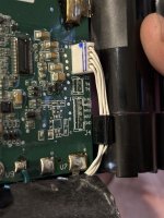
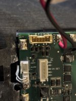
Found a few things on the board. Firstly, it talks to the controller/dashboard via Canbus. Pretty typical, potentially good news for aftermarket/DIY batteries. Found an unused header labeled J10 with pins 'pack-' and 'release'. Found another unpopulated header that appears to be... programming/JTAG header? 3.3V, SDWIO, SWCLK, REST, GND. Nothing obvious to reset the BMS.

A new battery is $321 (Honda Part number 08Z15-PR8-100R8) and I'm not entirely opposed to buying another one and sacrificing this battery to the DIY cause by putting an ANT BMS with CANBus in and seeing if I can make it work like OEM.

Any advice on getting this thing working again is welcome. The battery is a Dynapack model BL001.
 

Attachments

  • IMG_7378.jpeg
    IMG_7378.jpeg
    1.5 MB · Views: 17
  • IMG_7381.jpeg
    IMG_7381.jpeg
    1.1 MB · Views: 16
  • IMG_7379.jpeg
    IMG_7379.jpeg
    1 MB · Views: 18
Oh no, You fried your Honda? I had a chance to ride one last December. They are kind of fun,

I am leery of batteries that have a Canbus as I know nothing about it. Maybe Honda's famous warranty will help you get a new battery.

Same process whether it's a smart or dumb BMS. Did you check all the group voltages to see if they are balanced, and within the operating range above 3V and under 4.2V. I see only V0-V10 on your picture, indicating a 36V battery with 10 series groups, but I've read that the Motocompacto is 48V with 13 series groups.

Hope Honda comes thru, even if it was user error.

IMG_4627.JPG
 
Last edited:
It's a smart BMS. The CANBus is used to stream State of Charge to the dashboard, I don't believe it does anything else. The scooter will actually run without the canbus signal it just flashes a constant error message. If I hook up an arbitrary 36v battery to the battery connector the scooter runs again.

All groups are within a tenth of a volt of each other (my meter isn't very precise)

I kinda blatantly broke the warranty by taking stuff apart and modifying it. I doubt Honda would throw me a bone on this, and I'd kinda like to figure out how to actually fix the problem.

Modern version of this?
View attachment 347326
Yup! Very cool little things. Very well built, still kind of expensive for what you get at $950.
 
Update: I traced the path from pack+ to battery+ and found this 30a surface mount fuse in between them


Between VP and the fuse I get continuity, when I measure VP to the other side of the fuse I get pack voltage. When I measure VP to the heating element i also get pack voltage. Not entirely sure what to make of that, but it seems like a blown fuse to me. Fortunately it is on an area of the board that is not conformal coated. I may borrow a hot air station and remove it and just bypass it for the moment to see if that gets the battery functional again.
I think that makes sense. When the BMS triggers that fuse, it ties the heater to ground, which puts pack voltage across the heater, which means after triggering, the output side of the fuse could be tied to ground, and the battery side would of course still be connected to battery positive.
 
I'll have to check out the Motocompacto when available. What's the heating element for? As for checking the fuse, why not check continuity with power off using an ohm meter?
 
I think that makes sense. When the BMS triggers that fuse, it ties the heater to ground, which puts pack voltage across the heater, which means after triggering, the output side of the fuse could be tied to ground, and the battery side would of course still be connected to battery positive.
That makes a lot of sense. I hope you're wrong about the BMS triggering it though, because then replacing it will just result in another instant blow and means the battery has effectively bricked itself. I may just use a rework station to remove the fuse for now and bridge the main terminals. There's still a 20a fuse inline of the power leads.

Interestingly I went and poked at it some more with a DVM yesterday and now I'm getting 8v across the fuse. Not sure what changed there. My CAN sniffer came in today so I'm going to see if I can detangle how this thing communicates with the rest of the Motocompacto.
 
This is a bit off-topic, and I apologize for that, but I think that 100percentjake might be the only person online anywhere who has enough expertise to answer my question. I was doing range tests on my Motocompacto yesterday and the day before. The first test was using Mode 1 and I just made one lap after another after another on a one-mile loop near my house. I was pretty much running flat out at 11 mph, only stopping once per lap to write down my observations. When the battery charge hit 20%, I got the warning that the motocompacto would stop when battery percentage reached 5%. Sure enough, it stopped, right on the money at 5% battery charge. The dashboard was still lit, the headlight was still flashing, Bluetooth was still running, and everything seemed as it should. I walked the Motocompacto home and charged the battery back to 100% overnight.
The next day, I repeated the test, this time in Mode 2, pretty much flat out at 15 mph, again, stopping only once per lap to record the data. As you would expect, battery percentage fell lap after lap, but somewhat surprisingly, only at a slightly faster rate. I got the expected battery warning at 20% that the Motocompacto would stop at 5%. Battery level dropped from 20% to 7% very quickly, unlike during the previous test however. I started my last lap at 7% battery charge, expecting to go about 100 yards. At 100 yards, the Motocompacto stopped, but the dashboard, headlight and tail light went out, and Bluetooth disconnected. The last reported battery charge was 7%, and since Bluetooth died, I don't know what the final battery charge was. In any event, the Motocompacto is now un-chargeable. When I plug in the charger, I get about 6 blinking green lights, then a solid orange, then 5 blinking greens, and then solid green. Solid green is meant to indicate that the charger is either not plugged in or else the battery is fully charged. It is definitely not fully charged, since I have only had the charger connected to the Motocompacto for a few minutes.
I would have thought that if the main battery fuse was blown, the charger would not realize that it was plugged into the Motocompacto, but clearly it does, as the charger starts blinking like it should when I first plug it in.

Question for 100percentjake: Given that long story, does it seem possible that only the main fuse is blown, or is it more likely that the battery is damaged. I have an expensive wrap on the Motocompacto and before take it apart to check the fuse, and break a lot of tabs on the side panels. I'd like to know your advice, much appreciated.
 
Sounds like you have cells in the battery that have dropped below the BMS's safe-to-recharge LVC point, so it has turned the input off to prevent possible cell damage that could result in a fire. Based on PaulD's comment, it may do this by blowing the fuse to "brick" the pack and prevent further operation that could put people at risk. (most BMS just turn the charge / discharge FETs off and wont' turn them back on).

This usually happens because the cells were not matched to start with (most battery builders don't do this), and instead depended on the BMS to keep them balanced during each recharge (which can only happen if the pack is left on the charger long enough for this to happen, which can take hours or longer (sometimes much longer), depending on how mismatched the cells are). (balancing itself doesn't fix the problem, it only makes them all the same voltage at full charge, rather than making all the cells equally capable, which requires matched cells to do, and matched cells wouldn't need balancing).

While most BMS do have balancing function built in, many don't, and those cannot even do the above, so a battery with a mismatch / balance issue only gets worse and worse every usage cycle.
 
I appreciate the info. If I take the Motocompacto apart, the fuse is easy to change. If it turns out that the fuse is blown, and I replace the fuse, how likely is it that the battery will then take a full charge?
 
Depends on why the fuse blew.

If it just blew because the system was overloaded, then the system is probably perfectly fine (the fuse did it's job) and as long as it's not overloaded again it would operate normally.

If it blew because the BMS did it on purpose to prevent the pack from being used, then if the BMS still detects the problem condtion and still does wahtever it does that blows the fuse, it would jsut blow again.

If the BMS blew it for protection but has that as only an at-that-moment type of protection, and doesn't do this until it *transitions* to this state again, then it's expecting the problem that triggered it's protection mode to be fixed *before* replacing the fuse, and may not be able to protect against the existing problem, and cells could be damaged, etc.

Wihtout finding out why the fuse blew, it's hard to say if it will work normally, correctly, or at all, or if it is safe to keep using even if the fuse doesn't blow again. :/
 
Thanks again. I think I will go over and talk with my Honda dealer this morning. I need to find out if the mechanics there have a resource who understands the BMS who is not available to me. I also want to make sure that they know how to split the side panels apart without breaking the tabs. The workshop manual shows where all the side panel clips are located, and also shows the location of the fuse:
https://www.collegehillshonda.com/instructions/motocompacto/2024-motocompacto-service.pdf
At this point, I don't know if the fuse is blown as I haven't split the panels apart. My guess based on the information here is that it is blown, and my experience says it wasn't blown from an overload. I wasn't climbing a hill when the Motocompacto stopped, and I was rapidly approaching the 5% battery protection stop. My guess is that the battery went below 5% skipping the protection stop step and the fuse blew. If that is the case, and the mechanics don't have an answer, my inclination would be to put in a new fuse and see what happens when the Motocompacto is put on the charger.
 
I left the Motocompacto with Honda a week ago, and they hadn't looked at it yet, so I asked them today if I could have a look at it, and they said ok. I pulled off the Motocompacto side panels, and the fuse was not blown. I removed the battery, but don't have a wiring diagram for it. It has a pair of heavy gauge wires leading to a yellow plug. The fuse is inline in the red wire. There is no voltage at the yellow plug. I would think that there would be some, even if the battery was dead. There are two other black connectors, one with three light gauge wires (red, black, blue), and the other with 6 light gauge wires (red, black, white, gray, blue and green). Since the voltage at the yellow plug is zero, my hunch is that there is some sort of relay inside of the battery box that is closed by some action on one or both of the black plugs. Does anyone know of a wiring diagram for the Motocompacto, or have advice?
 
There are two fuses on a motocompacto. The one you can see on the battery leads is a normal automotive style blade fuse. The second one is inside the battery case itself. This one will blow due to an over-current condition like a normal fuse *or* the microcontroller inside the battery can kill the battery by intentionally blowing the fuse itself. If you have 0v on the battery cables it is very likely this has tripped like mine has. I believe under normal conditions a "powered down" battery still outputs 1-2v until woken up by some sort of signal from the controller, but don't quote me on this because I have yet to attempt to fix my battery and see if the fuse can be replaced or bypassed.
 
100percentjake, Man, that is much appreciated info. I will take the battery apart today and let you know what I find. You might be the only person in the USA who knows this stuff, much appreciated. I just started taking it apart, and what I hoped were two locating pegs in the top (one at each corner) must be plugs to document tampering. I think I will find a screw under each. Next step is to carefully drill through those plugs at each corner and see if there are screws underneath. Update: I didn't need to drill out those corner plugs. I was able to remove them with a pick. Underneath the plugs, I found Phillips head screws identical to the rest of the cover screws. This looks pretty tough without a wiring/logic and theory document. I don't see an obvious fuse, just many connections to the circuit board. Perhaps there is a fuse on the circuit board:

BatteryCoverOff800.JPG
 
Last edited:
When I take out the circuit board and measure the voltages at the points in this next picture, I am worried that all the cells are indeed in balance, so I don't see an out of balance condition. I also don't see any fuse, but there is no voltage at the red output wire. I am starting to worry that the battery is ok. What do you think?:
CircuitBoardVoltsA800.JPG
 
Perhaps there is a fuse on the circuit board:

Pretty sure (but not certain) that in the OP's pics in the first post, the P 020-J part is a fuse. I couldn't find (in a 30-second google) any info on that part number, but that doesn't mean much. :)
 
When I take out the circuit board and measure the voltages at the points in this next picture, I am worried that all the cells are indeed in balance, so I don't see an out of balance condition. I also don't see any fuse, but there is no voltage at the red output wire.
If theres no voltage there, relative to the *battery cell block* negative (not just the main output negative), then start probing at each trace and part you can visually see from that point back to the cells. At some point you will start finding a voltage. Or do it the other way--start measuring from the cell block positive until you stop finding a voltage. At that spot you've found what is blocking it, and then you can post a pic with an arrow and the voltage measurements on either side of it, and we can start reverse-engineering that section to see why. :)

If you get a voltage at the positive output wire when you have the meter negative on the battery cell block negative, but *not* when you have the meter negative on the main negative output wire, then that means like most BMS the switching, etc., is in the negative wire, and something has turned that off, for whatever reason.
 
The black main output wire and the battery cell block negative (what I call the ground post) act like they are hard wired together. The only way to debug this further is to unsolder all the cell blocks to lift up the main circuit board.

(Edit) I just went back at looked at the OPs posts looking for a P020-J. I need to read all of his posts in this topic again, as I may find my answer by reading them again.

(Edit again) I think what 100percentjake is saying is that there should be no voltage on the red wire if the 30 amp surface mount fuse is blown. I followed his link to the description of the fuse, but I can't see well enough to find it on the circuit board. Based on size and shape, is this the fuse? It would be most appreciated if Jake could confirm this and also that he sees no voltage on the red wire. If that can be confirmed it will save me from taking a second Motocompacto apart.
1710940177789.png
 
Last edited:
The final thing I need to know is for a good battery, where all the connectors are disconnected from the Motocompacto, what is the voltage between the black and red main wires that go to the yellow connector? It sounds like I will have to disassemble one of my other Motocompactos to get the answer.
 
The black main output wire and the battery cell block negative (what I call the ground post) act like they are hard wired together. The only way to debug this further is to unsolder all the cell blocks to lift up the main circuit board.
They may be; if this BMS doesnt' use FETs to cut off the output but instead just tells the controller to stop. But if it does use FETs, it's MUCH simpler and cheaper for them to use them in the battery negative than the positive (requires different FETs and/or a different type of gate drive circuitry).


I can't read the markings on the item you've marked in that image, even using the one from the OP's post which is pretty high-res. But it looks like one trace from it goes to one of the large solder pads nearby, and the rest of it appears to be connected to the PCB plane around it.

If it's a fuse, and if it's blown, it will have a different voltage on each side of it, and/or no continuity. (continuity isn't safe to test on a board connected to a battery, as the voltages present on different sides of something without continuity can blow up your meter). If it's not blown it will be identical voltages and continuity.

If it's a diode, or capacitor, it may also have different voltages on each connection. A resistor will only have different voltages if there's current flowing thru, otherwise they'd be the same.

(Edit) I just went back at looked at the OPs posts looking for a P020-J. I need to read all of his posts in this topic again, as I may find my answer by reading them again.
From this image in that first post, I circled it in red. I don't know that it's a fuse, as I didn't find data matching that marking, but it has the shape including the little indents that I have seen on various SMT fuses before.


There are two large SMT resistors "above" it in the image, which may be being used as shunts of some type (they're 200ohm, AFAICT; if wired in parallel that'd be 100ohm total); if not shunts they're at least carrying some current to have to be that big.
1710985201808.png
 
They may be; if this BMS doesnt' use FETs to cut off the output but instead just tells the controller to stop. But if it does use FETs, it's MUCH simpler and cheaper for them to use them in the battery negative than the positive (requires different FETs and/or a different type of gate drive circuitry).


I can't read the markings on the item you've marked in that image, even using the one from the OP's post which is pretty high-res. But it looks like one trace from it goes to one of the large solder pads nearby, and the rest of it appears to be connected to the PCB plane around it.

If it's a fuse, and if it's blown, it will have a different voltage on each side of it, and/or no continuity. (continuity isn't safe to test on a board connected to a battery, as the voltages present on different sides of something without continuity can blow up your meter). If it's not blown it will be identical voltages and continuity.

If it's a diode, or capacitor, it may also have different voltages on each connection. A resistor will only have different voltages if there's current flowing thru, otherwise they'd be the same.


From this image in that first post, I circled it in red. I don't know that it's a fuse, as I didn't find data matching that marking, but it has the shape including the little indents that I have seen on various SMT fuses before.


There are two large SMT resistors "above" it in the image, which may be being used as shunts of some type (they're 200ohm, AFAICT; if wired in parallel that'd be 100ohm total); if not shunts they're at least carrying some current to have to be that big.
View attachment 349534
amberwolf, Thanks, much appreciated. I would never have been able to spot that without your help. I will check the voltages on either side of it first thing later this morning. I still need to know if on a normal working Motocompacto battery, is there no voltage on the main red lead out of the battery when it is out of the Motocompacto and all battery leads have been disconnected. If I can confirm that a working battery has voltage on the red lead, then I can be sure that mine is bad.
 
Not much progress today. Both the P 020-J that is circled in red, and the two 201 resisters are coated with heavy plastic. I had to puncture the plastic coating with an X-Acto knife to reach the solder, and I could detect small voltage on the side of the P 020-J pointing to the right, but not on the other side that points to V3. Tomorrow, I will take apart a second Motocompacto, but not remove it's battery. Rather, I will just test the voltage between the red and black main leads on a good battery, with the other plugs still connected to the Motocompacto and also with the other plugs disconnected. If there is no voltage on the main red wire, then I will probably punt, assuming that the red only becomes hot when the throttle is opened. I am not sure what I will do then, probably take my findings to the dealer and wait a few weeks or months until some other Motocompacto owner has the same problem as mine, and the owner or the dealer network solves his problem and can share the solution with the other Honda/Acura dealers. At this point, I still don't know if the battery in the problem Motocompacto (#1) is bad, or if there is some other problem with it. I still have been unable to find a circuit diagram of a Motocompacto, and all the wires disappear into the frame, so it is hard to trace them without completely taking the whole thing down and drawing my own circuit diagram. If the red wire is hot on a good battery, then I will order a battery, and wait for it to come in, again, that might be weeks or months. I don't think I will try putting the battery from Motocompacto #2 into the bad one (Motocompacto #1), as I think I'll just put #2 back together in what I hope is a working state. I am tempted to just put battery #2 into Motocompacto #1 and see what happens, but then I might end up with two blown up Motocompactos.
 
Last edited:
Back
Top