
You are using an out of date browser. It may not display this or other websites correctly.
You should upgrade or use an alternative browser.
You should upgrade or use an alternative browser.
Emerson/Vertiv R48-series CAN programming?
- Thread starter Tomblarom
- Start date
All the rectifiers are not very precise in measuring current. I know from other companies that the values vary by plus or minus 1,5A.
Voltage reading is more accurate. It is around -0,1 to +0,3V to the voltage setting.
I programmed nearly 120 rectifiers from Eltek , Huawei , Vertiv and Megmeet in the last two years and checked their voltages unloaded and also the current settings with load applied. The best thing was all of them always reached the claimed output power.
Last edited:
I had the same series connected voltage problem during my first tries with the Eltek 48V 3kW Frontend Version, but only under full load. If one of them drops under 30V they reduce the output current to 50%, and at this point the voltage drops and on the other the voltage rises
Last edited:
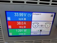
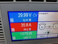
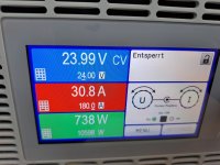
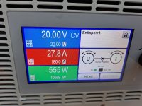
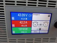
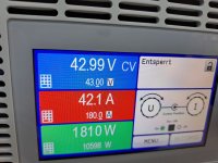
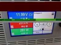
The vertiv r48-2000e3 ,and the others to, reduce the output current when the voltage drops.
At 10V the r48-2000e3 drops down to 20A. It was set to full current.
At 10V the r48-2000e3 drops down to 20A. It was set to full current.
Attachments
qwertyvitas
1 µW
Hello! I have Emerson R48-1000 and mcp2515 CAN from aliexpress.
When I connect my rectifier with arduino, I see this:
But I can not decipher the RX ID commands that the rectifier sends.
What is encrypted here 0x02 0xF0 0x00 0x00 0x3A 0x80 0x00 0x00 for example?
When I connect my rectifier with arduino, I see this:
TX ID: 0x0607FF83 Length: 8 Data: 0x03 0xF0 0x00 0x21 0x42 0x48 0x00 0x00 - excellent works and set 50.0V on 30 sec15:37:43.619 -> RX ID: 0x0707F803 Length: 8 Data: 0x04 0xF0 0x01 0x5A 0x00 0x00 0x00 0x00 Z
15:37:46.258 -> RX ID: 0x0707F803 Length: 8 Data: 0x02 0xF0 0x00 0x00 0x00 0x00 0x00 0x00
15:37:46.755 -> RX ID: 0x0707F803 Length: 8 Data: 0x03 0xF0 0x10 0x5A 0xCB 0xA7 0x05 0xB9 Z
15:37:49.265 -> RX ID: 0x0707F803 Length: 8 Data: 0x02 0xF0 0x00 0x00 0x00 0x00 0x00 0x00
15:37:52.308 -> RX ID: 0x0707F803 Length: 8 Data: 0x02 0xF0 0x00 0x00 0x00 0x00 0x00 0x00
15:37:52.705 -> RX ID: 0x0707F803 Length: 8 Data: 0x01 0xF0 0x00 0x00 0x3A 0x80 0x00 0x00 :
15:38:00.345 -> TX ID: 0x0607FF83 Length: 8 Data: 0x03 0xF0 0x00 0x21 0x42 0x48 0x00 0x00 !BH
15:38:00.345 -> RX ID: 0x0707F803 Length: 8 Data: 0x01 0xF0 0x00 0x00 0x3A 0x80 0x00 0x00 :
15:38:01.404 -> RX ID: 0x0707F803 Length: 8 Data: 0x02 0xF0 0x00 0x00 0x3A 0x80 0x00 0x00 :
15:38:10.539 -> RX ID: 0x0707F803 Length: 8 Data: 0x02 0xF0 0x00 0x00 0x00 0x00 0x00 0x00
But I can not decipher the RX ID commands that the rectifier sends.
What is encrypted here 0x02 0xF0 0x00 0x00 0x3A 0x80 0x00 0x00 for example?
thnorthstar
10 µW
If it is not a problem for you, can you share the codes and documents you made with Arduino?Hello! I have Emerson R48-1000 and mcp2515 CAN from aliexpress.
When I connect my rectifier with arduino, I see this:
TX ID: 0x0607FF83 Length: 8 Data: 0x03 0xF0 0x00 0x21 0x42 0x48 0x00 0x00 - excellent works and set 50.0V on 30 sec
But I can not decipher the RX ID commands that the rectifier sends.
What is encrypted here 0x02 0xF0 0x00 0x00 0x3A 0x80 0x00 0x00 for example?
AshevtsovS
1 µW
Hi!
How to correctly set the power supply unit to a constant voltage? According to the instructions, it was possible to set the voltage value to 58.8V, the unit outputs this voltage, but after rebooting it resets to 53.5
How to correctly set the power supply unit to a constant voltage? According to the instructions, it was possible to set the voltage value to 58.8V, the unit outputs this voltage, but after rebooting it resets to 53.5
CAN-ID 06 07 FF 83
1. Data 03 F0 00 21 42 50 00 00 online-voltage value gets lost after 30 seconds , just to see the changes
2. Data 03 F0 00 24 42 50 00 00 offline voltage Setting Voltage permanent to 52,5V
this works between 42 24 00 00 min 41V and 42 6A 00 00 max 58,5V
You can also only send the offline value command, but then you have to wait 30 seconds until the rectifier changes the voltages.
If you set the offline voltage and it looses this setting, either you set a to high value or the rectifier is not ok
AshevtsovS
1 µW
Everything is correct, I set a constant voltage of 58.5V using the command:
"CAN-ID: 06 07 FF 83
Data: 03 F0 00 24 42 6А 00 00 ". After 30s, the rectifier changed the voltage. But after restarting, it reset the value to 53.5V again.
It turned out that 58.5V was a lot for him.
I set 58.4 - and he remembered it even after rebooting.
Thank you!
"CAN-ID: 06 07 FF 83
Data: 03 F0 00 24 42 6А 00 00 ". After 30s, the rectifier changed the voltage. But after restarting, it reset the value to 53.5V again.
It turned out that 58.5V was a lot for him.
I set 58.4 - and he remembered it even after rebooting.
Thank you!
Pham Tuan Anh 65
1 µW
You use Data: 03 F0 00 21 42 6А 00 00 ( Equalize Charge Voltage command ) will set DCout = 58.5 after restarting ;and Data: 03 F0 00 24 42 6А 00 00 (default voltage command ) will set DCout = 58.5 when running offlineEverything is correct, I set a constant voltage of 58.5V using the command:
"CAN-ID: 06 07 FF 83
Data: 03 F0 00 24 42 6А 00 00 ". After 30s, the rectifier changed the voltage. But after restarting, it reset the value to 53.5V again.
It turned out that 58.5V was a lot for him.
I set 58.4 - and he remembered it even after rebooting.
Thank you!
Sorry no Arduino , Rapsberry or ESP program from my side,I use a USB to CAN converter and my laptopFrame ID 06080783 or 0607FF83 speed 125kB/s
Baud rate see above and you need to set extended frame , at least in my tool.
I use the canalyst 2 for programming.

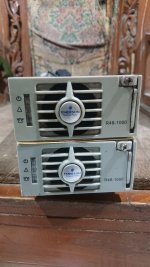
Yours is the old version.
Good to know they work with the same can codes.
The new one is 41x52x152mm and only 0,65kg
Only problem with two psu in series is starting at low SOC, sometimes one PSU stays at 43V and the other drops down to 25V and so it reduces the output current.
Good to know they work with the same can codes.
The new one is 41x52x152mm and only 0,65kg
Only problem with two psu in series is starting at low SOC, sometimes one PSU stays at 43V and the other drops down to 25V and so it reduces the output current.
Last edited:
crossy7980
1 µW
Hi Guys/Gals.
New kid on the block here with an Emerson R48.
I can talk to it and set the output voltage, current limit etc. thanks to this and a couple of other forums.
It's currently hooked to a Wemos D1 mini via an MCP2515 CAN interface board.
So, has anyone been able to decode the messages coming FROM the R48?
My prototype lash-up, yes, I do make notes on my desk, never a pad when you want one and my aging brain has bad RAM
The yellow wire is a mod to send 5V to the driver device, it does work on the 3.3V from the Wemos but isn't specified to 3.3V.
crossy7980
1 µW
With many thanks to @dominik h post earlier.
To read from the R48
Send to 06000783 => 01 F0 00 xx 00 00 00 00 xx = measurement No.
Response from 060F8003 <= 41 F0 00 xx yy yy yy yy xx = measurement No. yy yy yy yy = value
EDIT - corrected the response address
xx =
01 = output voltage
02 = output current
03 = output current limit
04 = temperature in C
05 = supply voltage
06 =
07 =
08 =
09 =
Last edited:
Hai friend.. I want to ask you, I have the same problem when connecting in series, 1 psu 43v, 1 other psu drops to 33v. The current is only 7.5a from a maximum of 20a. is this normal?Yours is the old version.
Good to know they work with the same can codes.
The new one is 41x52x152mm and only 0,65kg
Only problem with two psu in series is starting at low SOC, sometimes one PSU stays at 43V and the other drops down to 25V and so it reduces the output current.
What if I add 1 psu 48v 40a set to 43.8v, then I series it with the 2 previous psu that I paralleled at 43.8v to make it 87.6v 40a, will the current increase during the charging process, especially when low soc?
My battery is lifepo4 cylinder 24s 22ah. charging rate 1C. My target is to make 87.6v 20a charger.
Thank you in advance.
The best way would be to use a 24V rectifier that can be set to 28-30V or a 30V constant current power supply with 20A or 40A and put that in series with one or two 48V vertiv rectifiers. Then set the 48V rectifier to its upper voltage limit, and then you can be shure that it starts charging with higher current. If your battery is at 65V your rectifier starts with 35V and can not drop lower.
See the voltage/current chart from the Vertiv R48-1000E3
Sorry I have not found a chart for the old version

See the voltage/current chart from the Vertiv R48-1000E3
Sorry I have not found a chart for the old version
Last edited:
I am using an Eltek 24V and an Eltek 48V rectifier in series without any problem.
Only problem I see with having PSUs in series is, when one powersupply dies or shuts the output off, the other could probably see the full battery voltage and then the output protection could be triggered and if there is a varistor and a fuse as protection inside they will blew. But this problem exists if you use rectifiers with the same or with different voltages.
Only problem I see with having PSUs in series is, when one powersupply dies or shuts the output off, the other could probably see the full battery voltage and then the output protection could be triggered and if there is a varistor and a fuse as protection inside they will blew. But this problem exists if you use rectifiers with the same or with different voltages.
Last edited:
Hello everybody, I have good Arduino and ESP programming skills. But I have not much knowledge about handling rs485 code communication. I have 5 units AA27530L and one R48-3200e and would like to be able to adjust the voltage and output current if possible. I would be willing to write a program, possibly with display and/or serial read via arduino ide or VS Code, but I would need more precise and complete instructions about the communication. cheers, Lisa
Similar threads
- Replies
- 5
- Views
- 1,653
- Replies
- 0
- Views
- 907
- Replies
- 8
- Views
- 5,049