people are misled by labels so my hi-skool fizziks prof always made it a point when referring to motor/generator diagrams as mogen.
You are using an out of date browser. It may not display this or other websites correctly.
You should upgrade or use an alternative browser.
You should upgrade or use an alternative browser.
End turns bad?
- Thread starter Buk___
- Start date
madin88 said:Luke has explained the thing with the torque already plus he described an experiment. PLEASE DO IT!!!
madin88: I didn't need to, but I did perform Luke's experiment*; and I didn't need to purchase a 'spare' motor and rip it apart; nor buy a dynamometer to do it.
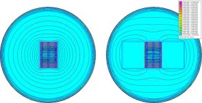
Here is a simulation of Luke's experiment*:
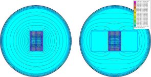
The (cross-section of) the tooth on the left has 50 turns of 1mm^2 copper wrapped tightly around it with 10A running through it.
The tooth on the right, has 50 turns of 1mm^2 copper wrapped tightly across the tooth faces and looping far away around the 'ends' of the teeth which also have 10A running through them.
The upshot is that they they show (me) -- via the concentration of flux lines around the tooth -- that the field intensity within the core area is greater in the left hand core than the right, because neither the copper in the conductors nor electric field it carries, care which side of the iron core they are on; the only thing that counts is the proximity.
But it does not make for a very compelling picture, and given the earlier condemnation through faint praise of math and simulation, me stating that the integral of B over the left-hand core is substantially higher than that within the right-hand, loose-turns core or providing numbers like these:
Code:
Left tooth:
x-component: 9.67603e-012-I*4.68351e-012 Tesla meter^3
y-component: 8.69034e-011+I*7.40813e-012 Tesla meter^3

Right tooth:
x-component: -3.31067e-011+I*9.42613e-012 Tesla meter^3
y-component:  3.25291e-011-I*5.01319e-012 Tesla meter^3
They'd either be ignored, or we'd get into some irrelevant debate about the form of the presentation, or their applicability to reality. (The former is the way they are presented by the FEA software; and FEA is the way motors (and pretty much everything else) is design in the modern world.)
madin88 said:The point is that you simply cannot compare a wound teeth from a stator with a normal coil, because only the magnetic force (or field lines) which are moving the rotor play a role for the mechanical power, the other fields are cancelling out.
With respect -- and I've tried very hard to show everyone here respect, even the male member that did his utmost to derail this thread right up to the point his ad hominim attacks turned into a puerile attempt at character assassination,
Your statement above gives me nothing to argue against. It offers no evidence, no analogy, no physical or mathematical basis.
It is un(dis)proveable, unrefutable; and unratifiable. In short, it is undeniable...
It is your opinion and you believe it.
But I didn't come here to prove this to anyone else, I came to see if anyone could dissuade me from the conclusion I was (and then had) reached.
So far (from memory, I might have missed something), with the exception of major -- to whom I am inordinately grateful despite that we disagree -- no one has offered anything more that their unsupported opinion -- and a few insults.
And (concurring with Alan B) I'm quite sure that major highlighted where the source of the misunderstanding arises.
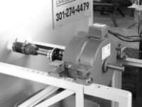
In (some) brushed motors with drum cores, -- like this:

The windings do not go around the 'teeth', but rather wrap around the motor ends from one side to the other, something like this:
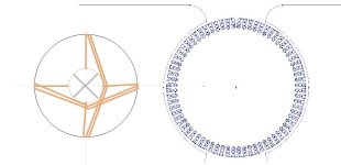
In that type of motor, the motive force *IS* produced in large part by the long straight conductors cutting the field lines that span side to side, in close proximity to the magnets producing Lorentz forces that act directly upon the drum rotor. In this case, those long diametric end turns do not contribute to those Lorentz forces.
They do contribute to the field strength within the drum core, and with the mechanical commutation, that sets up a "bar magnet" at right angles to the permanent magnets, the 'ends' of which are attracted to the PMs, and that adds to the torque created.
One day I'll more fully model that type of motor and work out what proportion of the torque produced derives from Lorentz forces and what from simple attraction/repulsion.
But, BLDCs don't work that way. With the coils in the stator, any Lorentz force acting on them -- small as it is given their remoteness from the magnets, is dissipated trying to move the immovable object.
And the coils don't cross the diameter, but rather wrap around the circumferential teeth. The torque is produced entirely by the actions of attraction and repulsion (cross-linking) between the field lines emanating from the heads of the teeth and the rotor magnets; and the strength of that cross-linking is determined by the density of the flux with the teeth. And every part of every turn -- ie. the full loop, all 4 sides -- contributes to that flux density.
madin88 said:Thus, the Endturns do nothing in terms of that.
Sorry, but I respectfully disagree.
*I might have politely suggested that Luke -- whom probably has a 'spare' motor or 5 lying around, and access to a dynamometer -- might carry out his experiment physically and report his finding back here for all to see; but then given this is a man who can't admit he was wrong in calling the Honda TFM motor, a PMSRM --even when linked to the document by the Honda engineers that designed and built it -- what chance he will report his (true) findings, even if he performed the experiment?
JanComputerman said:Build it and it will spin!
It's not a case of just making it spin; but rather making it spins at the right speed at the required voltage; with the right torque for the required amperage. Twice!
My motor design --such as it is -- combines two motors in a single hub, each with different characteristic, and linked by a planetary differential. Not a unique idea by a long chalk, but one that -- to my knowledge and research, has never been successfully built. Critical to its function is that the two motors can be coordinated -- by controller software -- to cooperate and not fight each other. With one motor spinning backwards half the time and forwards the rest and both motors spinning in opposite directions at different speeds when stationary; getting the motors characteristics correct, and coordinating them, is critical.
Will I ever build it? Probably not; though I have attempted to allocate funds to it from my limited income. Whether that comes to fruition depends whether we have any capital intensive problems this year as we have for the last 3 -- medical bills, boiler died, car smash.
It also depends very much on whether I can convince myself --through simulation and knowledge acquisition -- that it will work if built. I do not have the funds to throw cash at it; and I'm not one for passing the begging bowl to fund my half baked ideas. (eg. kickstarter
Martyn,
This is from: Mechanical Design of Electric Motors - Tong, Wei. (Page 242 & 243). CRC Press.
"4.4.5 Stator Winding One of the important parameters in stator winding is the slot fill ratio, which is defined as the percentage of the space occupied by magnet wires to the total available space of the slot. In order to lower the wire resistive loss and increase the power density, it is highly preferable to have the maximum copper fill, that is, maximum slot fill ratio. A winding end turn refers to the amount of the winding extending beyond each end of the stator’s magnetic core structure. Though the end turns are necessary to complete the electrical path within the winding, they contribute little to the motor torque output. Motor torque is only generated by the winding that lies within the stator’s magnetic core structure. Consequently, it is highly desired to minimize the length of the winding end turns. This can not only save the wiring material and lower the material cost but also reduce the copper loss and increase the motor efficiency. The shorter the winding stack length, the greater the impact of the end turn length on motor efficiency."
Buk___ said:With respect -- and I've tried very hard to show everyone here respect, even the male member that did his utmost to derail this thread right up to the point his ad hominim attacks turned into a puerile attempt at character assassination,
Your statement above gives me nothing to argue against. It offers no evidence, no analogy, no physical or mathematical basis.
It is un(dis)proveable, unrefutable; and unratifiable. In short, it is undeniable...
It is your opinion and you believe it.
But I didn't come here to prove this to anyone else, I came to see if anyone could dissuade me from the conclusion I was (and then had) reached.
I have this opinion from the papers which have been posted here, and those informations have approved what i already have believed.
Thats how it is and you should not ignore it, but i can understand that you want your own proof.
About the simulation:
Yes the vertical field lines (which should be the one important for the torque) look larger as on the left picture, but the numbers below are more confusing than meaningful (at least for me).
Voltron
1 MW
"My motor design --such as it is -- combines two motors in a single hub, each with different characteristic, and linked by a planetary differential. Not a unique idea by a long chalk, but one that -- to my knowledge and research, has never been successfully built."
Not to diminish your research, but that type of system is already in use, the NSK wheel motor for cars, and the Solomon Technologies drive system for boats being two examples..
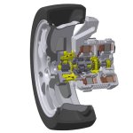
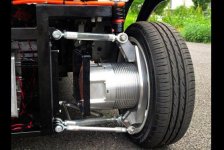
I'm not sure if the NSK counts as a planetary. but the Solomon setup def has one in between the two pancake motors... i.e. its not simply two motors coupled to a common shaft.
"Assume that you're driving the boat forward and looking at the front of the motor, which points to the bow. In the ST58, one ST Motor drives the ring gear and another ST Motor drives the sun gear. The planetary gear carrier connects to the drive shaft (PTO).
At motor speeds below 600 RPM, the sun gear turns counterclockwise (CCW), the ring gear freewheels, and the planetary gears drive the shaft clockwise (CW). The gear ratio is 2.6:1. Above 600 RPM, a controller switches the drive gears—the ring gear drives CW and the sun gear freewheels. Again, the planetary gear assembly continues driving the shaft CW, though at a ratio of 1.6:1. When the motor speed exceeds 650 RPM, the controller switches both sun and ring gears to drive CW, and the gear ratio becomes 1:1."
Not to diminish your research, but that type of system is already in use, the NSK wheel motor for cars, and the Solomon Technologies drive system for boats being two examples..


I'm not sure if the NSK counts as a planetary. but the Solomon setup def has one in between the two pancake motors... i.e. its not simply two motors coupled to a common shaft.
"Assume that you're driving the boat forward and looking at the front of the motor, which points to the bow. In the ST58, one ST Motor drives the ring gear and another ST Motor drives the sun gear. The planetary gear carrier connects to the drive shaft (PTO).
At motor speeds below 600 RPM, the sun gear turns counterclockwise (CCW), the ring gear freewheels, and the planetary gears drive the shaft clockwise (CW). The gear ratio is 2.6:1. Above 600 RPM, a controller switches the drive gears—the ring gear drives CW and the sun gear freewheels. Again, the planetary gear assembly continues driving the shaft CW, though at a ratio of 1.6:1. When the motor speed exceeds 650 RPM, the controller switches both sun and ring gears to drive CW, and the gear ratio becomes 1:1."
Miles said:Martyn,
This is from: Mechanical Design of Electric Motors - Tong, Wei. (Page 242 & 243). CRC Press.
"4.4.5 Stator Winding One of the important parameters in stator winding is the slot fill ratio, which is defined as the percentage of the space occupied by magnet wires to the total available space of the slot. In order to lower the wire resistive loss and increase the power density, it is highly preferable to have the maximum copper fill, that is, maximum slot fill ratio. A winding end turn refers to the amount of the winding extending beyond each end of the stator’s magnetic core structure. Though the end turns are necessary to complete the electrical path within the winding, they contribute little to the motor torque output. Motor torque is only generated by the winding that lies within the stator’s magnetic core structure. Consequently, it is highly desired to minimize the length of the winding end turns. This can not only save the wiring material and lower the material cost but also reduce the copper loss and increase the motor efficiency. The shorter the winding stack length, the greater the impact of the end turn length on motor efficiency."
So now you are quoting someone else's opinion. Someone who happened to write a book.
First the book and the quote. Including the one you cite, there are exactly 10 references to the term"end turn(s)" in the book.
- Page 30: Reducing the copper losses in the motor windings. This can be done by increasing the cross-sectional area of the conductor or by improving the winding technique to reduce the winding length, especially at the end turns.
- Page 35: This provides the average temperature of the whole winding, including the motor leads, end turns, and wires deep inside the stator slots.
- Page 221: The segmented lamination technology and single-tooth windings enable a motor to have signifcantly shortened end turns. This feature allows the motor to be much shorter, comparing with the long end turns found in conventionally random-wound servomotors.
- Page 242/243: The quote you cited above.
- Page 259: For radial air gap motors, the stator coils are wound axially through the stator slots, and the end turns of the stator winding are positioned adjacent to the stator end surfaces. The endbells and the motor housing form an enclosure to protect the stator windings and end
turns from inadvertent contact and grounding while providing a mounting surface for rotor bearings and shaft bushings. The endbells also prevent debris from entering the hollow interior of the stator and interfering with operation of the motor.
- Page 277: For the consideration of safety, a minimum clearance gap of 1.5 mm must be provided between the coil end turns and the endbell wall.
- Page 435: Rotor fan is casted together with the rotor conducting bars and end rings at each end of the rotor assembly for cooling motor windings, particularly winding end turns.
- Page 578: While the temperatures of stator windings at the middle and end turns approach 140°C, the temperatures of motor housing reach 110°C. The ambient temperature is controlled to maintain in the range of 25°C–30°C.
So, of the 10 references he makes, two relate to the affect of end turns on efficiency, and both are simply bland statements "they're bad"; with no source of that conclusion, nor reasoning behind it.
And look carefully at the other references -- and especially the pictures and diagrams around them. Notice anything? How they are mostly pictures of AC mains motors with the occasional brushed DC motor thrown in. See those huge bundles of end turns spanning large arcs of the rotor circumferences; rather than the neat, short, turns back around the other side of the same tooth of the stator that you see in all brushless DC motors?
So, now let's look at the man. I cannot find a DOB for him, but he completed his PhD in 1989, so born circa 1964, and in 2014 (when the book was released) approximately 50y/o. His bio reads:
"Wei Tong, Ph.D, PE is chief engineer at Kollmorgen Corporation, a subsidiary of Danaher Corporation, Radford, Virginia, USA. He is an internationally recognized expert on mechanical–electrical–thermal systems. A fellow of the American Society of Mechanical Engineers and a registered professional engineer in the state of Virginia, USA, Dr. Tong holds 28 US patents and 16 foreign patents. He presently serves as an associate editor of ASME Journal of Heat Transfer and International Journal of Rotating Machinery.
As a fellow (2006–) of the American Society of Mechanical Engineering (ASME), Dr. Tong has served on several ASME committees, including Heat Transfer under Extreme Conditions (K-18), Heat Transfer in Energy Systems (K-6), Aerospace Heat Transfer (K-12), and Long Range Directions and Issues in Heat Transfer (K-2). He was the chair of the K-18 Committee during 2006–2009. In 2006, Dr. Tong was appointed as an adjunct professor in the Department of Mechanical Engineering, Virginia Polytechnic Institute and State University, where he taught an undergraduate course on mechanical engineering design."
Now look at where he works(ed) at that time and their products: Kollmorgon Corporation. Notice that they are AC, and latterly, brushed DC motors. Stepper and synchronous motors.
He seems more thermal guy than motor designer, and author more than engineer. Is it possible that he is correct in the context of the optimisation of the rotors of AC stepper motors & brushed DC motors he is familiar with; but not so much is the context of the stators of BLDCs?
I'm not for one moment suggesting the book isn't excellent and the man a fine author and competent engineer; but isn't it possible that he is relating a design criteria that makes sense in the context of his experience, but not so much in BLDCs.
Possible?
Buk.
BTW: I have an idea that might seal this (part) of the discussion. I'll get back to you.
Voltron said:"My motor design --such as it is -- combines two motors in a single hub, each with different characteristic, and linked by a planetary differential. Not a unique idea by a long chalk, but one that -- to my knowledge and research, has never been successfully built."
Not to diminish your research, but that type of system is already in use, the NSK wheel motor for cars, and the Solomon Technologies drive system for boats being two examples..
NSK-wheel-hub-motor.jpg
nsk.jpg
solomon.jpg
I'm not sure if the NSK counts as a planetary. but the Solomon setup def has one in between the two pancake motors... i.e. its not simply two motors coupled to a common shaft.
I did say that the idea was far from unique. On the basis of no more than looking at your pictures, the two motors in these designs appear to be used to provide step changes in ratios (ie. gears). The intent of my design is that it constitutes an IVT -- infinitely variable transmission. (Again, not a unique idea.)
In this design both motors are driving their sides of the planetary differential continuously. When stationary, they drive in opposite directions, giving zero motion. To accelerate, the backwards driving motor slows down, allowing progressively more of the forward driving motor's (running at optimum efficiency) speed and torque to transfer to the output until the point where the backward motor reaches 0 rpm, and the full rpm/torque of the forward motor is being transferred to the wheel. (Still at its optimum efficient rpm.)
Then the backward motor reverses and starts driving forward. At this crossover point, the initially forward motor slows (quite rapidly) to somewhere close to the lower end of its optimum efficiency rpm band at the same time as the initially backward motor speeds up (forward and quickly enough to compensate for the forward motors slowdown) to reach the lower end of its optimum efficiency band. They then accelerate together to achieve higher speeds.
By using two differently rated motors -- one (initially forward) lower kV and one (initially backward) higher kV -- you can achieve good torque, with good electrical and thermal efficiency, over a much wider range of speeds.
Note: The intent here is to combine two smallish 100mm/120mm geared hub type motors in a single hub to provide the equivalent of a '201 wind' and a '328 wind' in a small, stealthy and economic package. Good climbing ability and descent top speed without a ton of weight, huge battery requirement or thermal issues at either end of the scale.
madin88 said:About the simulation:
Yes the vertical field lines (which should be the one important for the torque) look larger as on the left picture, but the numbers below are more confusing than meaningful (at least for me).
The thing you have to remember about that picture, is that it is a cross section through the teeth. (The view of the field around a a bar magnet that no one ever publishes.)
The north pole of the field with the tooth is pointing straight out of the screen and the south pole somewhere behind it. The field lines -- as in all such representations of magnetic fields -- represent lines of equal field or flux intensity -- like lines of equal height on a contoured topological map, or lines of equal pressure on a whether map.
And the closer to the source of the magnetic field (the bar magnet in those images; and in this case, the temporary bar magnet created by the electrical field in the conductor inducing a magnetic field within the tooth core -- they are, the higher their intensity, and the closer together they are, the greater their density.
And to produce torque, the desire is to achieve the highest density of field (lines) within the tooth core. These then emanate straight out of the screen at you, where they attract or repel the magnets on the rotor.
The number and close packing of the field lines in the left-hand example show that the field density within the tooth is much greater than in the right-hand example. This is proof positive to anyone who can read these plots that the end turns are doing very useful work.
My point is that top or bottom, left or right in this 2D cross-section is irrelevant; they all loop through the laminated tooth core, and contribute to the density of flux therein. It is that density of flux that drives the strength of the cross-linking field within the air gap -- that you need a 2D slice orthogonal to this one, or a 3D FEA image -- to see and appreciate, that controls torque production.
major
10 kW
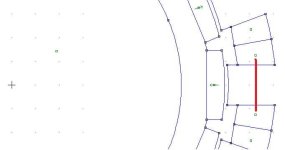
Yes. It might (for example) be a slice taken as shown in red in this inrunner model:major said:Buk,
EndLoopsFEA.jpg
Is this a cross section of a single tooth, the plane of which is perpendicular to the radius of the motor?
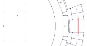 , but could equally well be an outrunner; or of any order.
major said:It also appears some of the field lines cross other field lines. Please comment how that happens.
Great question
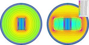
When the snapshot was taken, the model was simulating running at 100Hz, and the field lines arising from both the real and imaginary parts of the results were being plotted simultaneously. They are (slightly) different colors, grey versus black, but that information has been diminished or lost in shrinking the image for posting.
The overlapping is of lines arising from the imaginary part crossing those of the real part.
He's one of a run at 0Hz (no imaginary part):
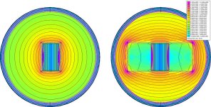
I've upped the amperage to make for a more compelling picture, but it shows the same thing.
Sorry for the confusion.
Miles said:Hanselmann 1.jpgThis is from Hanselmann "Brushless Permanent Magnet Motor Design" page 209
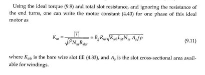
"Motor constant as given by (9.11) ignores the winding end turns. Since the end turns create ohmic losses but do not produce torque, they directly diminish motor constant."
He excludes the ends turn from the formula he derives, because he believes they are bad.
I cannot argue against what he believes, nor validate the veracity of his claims. Is he another formerly brushed motor designer who didn't notice that this part of the design methodology for them doesn't transfer?
Until someone can show me how a stator tooth is different to the classic iron-cored solenoid, repetitions of the same statement by different people does nothing to further the discussion.
I get that if its in a book, it is hard to argue against, but books have been wrong before.
And it wouldn't be the first time that books originally written for an older context have failed to catch up with the newer (or in this case, at least resurgent) technologies.
A trivial example that may ring true with some here: When MS released Windows NT(XP/Vista/...), they included an new command line processor (cmd.exe) that was a quite considerable upgrade from the previous DOS/Win95 processor, command.com. Five, and even ten years later, re-releases of books originally rewritten for DOS/Win95, and even new books by authors grounded in those older systems, still had whole chapters on using that older CLI, including tips&tricks&workarounds of its limitations, many of which had been addressed in the newer cmd.exe.
I've encountered similar persistence of outdated ideas in mechanical engineering handbooks; that often proclaim things like: "In it's 10th release with more than 200 changes and updates". Which means that at least some of the information in the last edition was wrong. Or at least is now wrong, subject to new information, different discoveries, changing practices; better working methods...
I'm not saying that is the case here; but it is the only explanation I have for the widespread nature of this notion. Of course, I may be wrong; but on the basis of everything I can do short of building a motor with either no end turns, or stupid long ones, and comparing it directly to an identical motor with normal ones; until I have a description or formula that demonstrates the BLDC stator teeth are not just directly analogous to solenoids; but are solenoids in every electromagnetic sense of the term, I will remain convinced that this is a case of misapplied reasoning.
Imagine this. The shortest way (reducing ohmic losses) to enclose the greatest area (to prevent saturation) would be to use round BLDC stator teeth.
Have you heard of spiral-wound (slinky form) cores? Imagine spiral-wound (eddy current reduction) round (maximising cross-sectional area) teeth, wound with round coils(minimising ohmic losses), threaded to screw into the stator hub. Too much?
Cheers, Buk.
(BTW: Did I hear that damn buzzing sound again somewhere?)
That would also likely increase motor size per watt of power capacity (and per foot-pound of torque) due to the loss of packaging efficiency.Buk___ said:Imagine this. The shortest way (reducing ohmic losses) to enclose the greatest area (to prevent saturation) would be to use round BLDC stator teeth.
billvon said:That would also likely increase motor size per watt of power capacity (and per foot-pound of torque) due to the loss of packaging efficiency.Buk___ said:Imagine this. The shortest way (reducing ohmic losses) to enclose the greatest area (to prevent saturation) would be to use round BLDC stator teeth.
I was thinking (always) in terms of small hub motors like Bionx and Qutes where the teeth are roughly square. Next best might be elliptical, but you right, it wouldn't beat rectilinear for packaging.
Buk___ said:(BTW: Did I hear that damn buzzing sound again somewhere?)
Hey, I was staying out of it till you goaded me 8)
Buk___ said:He excludes the ends turn from the formula he derives, because he believes they are bad.
Yet it's OK to dismiss *every* piece of literature on the subject because you *believe* they are wrong
Buk___ said:I get that if its in a book, it is hard to argue against, but books have been wrong before.
Fair point. I use the same argument to prove the universe works strictly according to astrological principles. Oh, and magnetism is a fallacy perpetuated by the illuminati, so your arguments about how motors work are wrong. Sorry.
Buk___ said:Note: The intent here is to combine two smallish 100mm/120mm geared hub type motors in a single hub to provide the equivalent of a '201 wind' and a '328 wind' in a small, stealthy and economic package. Good climbing ability and descent top speed without a ton of weight, huge battery requirement or thermal issues at either end of the scale.
Pls explain how the Kv of a motor effects its inherent potential for power/torque/efficiency. Bonus points if you include the phrase "torque wind" or "speed wind. Also, pretty please, explain how the extra mass and inefficiency of this complex gear assembly and two small motors out-performs a single, larger motor of equal system mass?
major
10 kW
Buk___ said:
Thanks. Couple of questions if you don't mind.
What does "or of any order" mean?
In the flux map of the cross section which you show, the flux lines in the tooth which would run radially in the motor and cross the air gap will be oriented perpendicular to the viewing screen. What information is displayed on the map concerning the B (or H) field in the thooth?
If I understand your analysis it involves only a single piece of a single tooth and some wire (with current). I can see there are x & y dimensions to the tooth, what is the z dimension?
Doesn't the entire magnetic circuit or at least whole symetrical section of it need to be modeled to obtain magnetic behavior in any part?
Thanks,
major
major said:What does "or of any order" mean?
Short hand for any valid combination of teeth and poles.
major said:In the flux map of the cross section which you show, the flux lines in the tooth which would run radially in the motor and cross the air gap will be oriented perpendicular to the viewing screen.
Short answer: yes. If they were represented in this view, they would just be dots.
Longer answer. My visual analogy is that the lines on these 2D plots are (somewhat) like a slice through an onion. If the tooth/solenoid/bar magnet is the core of the onion with the sprouts being the north pole and the roots the south; then in the normal 2D simulation viewpoint down the axle with the motor arrange radially around it . the flux lines through the core in this side view, flow south to north in nearly straight lines until they leave the core at the airgap tooth face. They then cross the air gap, pass through the nearest compatible magnet and loop back via the backiron and adjacent teeth.
Ie. the normal view is a slice through the onion vertically.
In this view, the slice is taken horizontally, so the lines are rings.
major said:What information is displayed on the map concerning the B (or H) field in the tooth?
In that particular image, it is B. You can just make it out at the bottom of the legend where it reads: Density plot: |B| Tesla.
(It would show |H| A/m^3 for the H.)
major said:If I understand your analysis it involves only a single piece of a single tooth and some wire (with current). I can see there are x & y dimensions to the tooth, what is the z dimension?
In a 2D sim, the Z is just a single number (in this case set to 50mm). All slices through that depth are taken to be identical. If you wanted to model the entire motor this way, you'd need to construct a different picture for each slice through the motor. Very laborious.
major said:Doesn't the entire magnetic circuit or at least whole symetrical section of it need to be modeled to obtain magnetic behavior in any part?
Certainly, if you are trying to characterise the motor and derive meaningful metrics, but at the mid point of a tooth, the permeance of the iron is so high relative to that of the air that surrounds it, that there is almost no mutual inductance between adjacent teeth, so as a demonstration that copper on the radials sides of the teeth adds to the field density within the tooth just as the copper on the axial sides does, it serves its purpose.
A perhaps better demonstration would be to model a cross section through 4 adjacent teeth. The central two powered in opposite directions (per the two power phases) and the outer two unpowered representing the third phase acting as return paths; but a 2D simulation in this plane would not calculate anything outside of the plane (eg. neither the back-iron in front of the plane, nor the stator hub behind the plane), so no return flux would show up in the outer two teeth, and the inner two would simply be mirror images of each other.
The field lines in the gap between them would be squashed together somewhat -- like squashing the side of two onions together -- and if I added directional vectors to the plot, the fields around the two powered teeth, the circles around them would flow in opposite directions due to the difference in the direction of the current flowing in the coils.
I thought about doing that; but it adds no useful information, but takes considerably longer to run due to the quadrupling of the number of nodes and elements in the mesh. I didn't feel the need to do that as the single tooth plot showed me what I expected to see.
If you feel it would be useful to you? I will look to do it tomorrow and throw it into a low priority background session and post the results when they eventually complete. Could be a day or three.
Cheers, Buk.
JanComputerman
10 W
This is some of what I know ...
Gearing = losses ... Avoid gearing!
More core material = more core losses
If your motor is only in the high 80's % efficient then two of them with gearing is going to lower the total efficiency and most likely raise the cost i.e. two controllers for two motors.
I have a few bldc motors made by a small company in PA. that are about 93% efficient and back in the early 2000's I worked with the president and gave him the idea how to make it more efficient and as a result increased the efficiency to about 96%. There are a few variations of the motor using twelve 1x1.2 inch magnets 1/4 inch thick single, double, triple, and even quadruple stack magnet rotors resulting in different rpm/volt and torque per amp as you would expect. These motors couple the rotor to the windings so well that if you short the phase wires together and try to turn the 7/8 inch diameter shaft with a vise grips you will have a hard time turning it. The old design was 15lbs 3 inches thick about 7 inch diameter totally enclosed in an aluminum case which can be heat sinked for cooling at high 6000+ watt power levels. The new ones go way beyond that.
My point ... If you know what makes a motor design efficient then do it and stop trying to make an inefficient design do something that it can't possibly do.
And just a little note from a recent post above ... I did make an air core (plywood) motor with a 12 inch diameter rotor with 36 1x1x 1/8 magnets and 1/2 turn windings using 10 awg wires and it spun so fast at 6 volts that the magnets flew off the rotor. Iron cores that big are really expensive!
JanComputerman said:This is some of what I know ...
Gearing = losses ... Avoid gearing!
More core material = more core losses
If your motor is only in the high 80's % efficient then two of them with gearing is going to lower the total efficiency and most likely raise the cost i.e. two controllers for two motors.
There are essentially 3 types of motor used on bikes and two of those three already use gears:
- Direct drive hubs.
The 500ci V8 shopping cars of e-bikes. Big, heavy, bullet-proof at the expense of efficiency. Fine once your speed gets up into double digits, and if you can take a long run-up to any hills you encounter; but around town, in mixed company at low speeds, stop-start traffic, pulling away uphill from lights and stop signs, they are turning so slowly that the are running very inefficiently.
Sure you can address that by sticking huge, high-voltage, high capacity battery packs on them -- like fitting a bigger gas tank on a those V8 shopping cars -- and you can fit heat sinks and cooling fluids to deal with all the heat created, but its all extra weight and doesn't address the the efficiency. It may cost pennies to charge a big pack; but then it cost pennies to fill your tank back in the early '70s. It's just repeating the same mistakes.
Or you can put tiny little wheels on your bike, with all the visual affects and disastrous ride and handling that gives, and you still need to double or treble your voltage to achieve even a moderate top speed.
. - Mid drives.
Mid drives re-use the bikes normal gearing with predictable consequences. That can be fixed with the added complication of addional left-side gears and chain.
Latterly, commercial mid drives are beginning to incorporate 2 stage reductions, and/or multi-speed gearboxes, but they mostly require special frames, still push bicycle drive trains to and beyond the design limits and for normal human beings preclude adding our own power to the mix much above about 30kph; and even for the Lance Armstrong-a-likes amongst us, require stupidly large chainrings and stupidly small sprockets to be able to keep up.
.
- Geared hubs.
Small (visually discrete), light (1/3 the weight of a DD) and gears to keep the motor spinning fast enough to be efficient, and to regain the torque you lost by going smaller diameter, through gear train multiplication.
The problem is, like small (~1l) ICE engines, you either gear them for acceleration, for buzzing around town, or you gear them for motorway speeds and they take an age to get there, or you fit 5 or 6 or more gears (and now turbo chargers) to try to spread the load.
In e-bike motor terms, the small Qutes come in various 'speeds': '201rpm', '260rpm', '328rpm'. The differences may be due to internal gear ratios, or the way the stators are wound, or a combination of the two, but whist the 328 might get to 40kph, it struggles when pulling away and going up hills. On the other hand, the 201 is great in stop-start and on hills, but struggles to get much past 20kph on an open road.
The rotors in the motors are barely 1/4th the width of the hub, the rest is taken up by a two stage reduction planetary gearbox; but why use mechanical reduction gears when we can use the flexibility of electrickery?
.
In that same (roughly 100mm wide, 120mm diameter) space, I can fit two motors, each with double the stator width of the Qutes, and a planetary differential. I don't need the two stage reduction, because the two motors operating in concert can produce an infinite number of effective gear ratios.
And all for a total weight maybe 25% more (say 1kg for a total of 5) than existing small geared hubs, because copper weighs more that steel.
Oh, and a second controller. But the state-of-the-art of controlling and coordinating multiple motors is the RC world, particularly quads/hexes/octos, where they use ESCcs that are a fraction of the weight of the typical e-bike controllers, so maybe a using two of those would actually reduce weight.
Using the same size battery packs (36 or 48V, 0.6to1.0kWh) as commuter e-bikes are using now, you get round town efficiency for greater distance and the ability to go faster when needed (at the expense of distance), all in a package that you can ride home if you run out.
It's the e-bike I want, and whether I ever get to build it really doesn't matter to me. The mental stimulation of learning new disciplines in my retirement is more than enough reason. The prospect of that I might get the e-bike I want at some point is just extra motivation.
liveforphysics
100 TW
Turning slow doesn't mean inefficient. You could have a tiny 4 pole 10,000rpm motor with the exact iron frequency power per mass as a 400 pole motor turning at 100rpm.
The forces end turns make on the tooth are in equal and opposite thrust-axis orientations on the rotor so they don't contribute towards rotational torque in the axis we care about for vehicle motion.
You can easily show this by winding a tooth that has end-turns that hang down however many feet away from the motor you wish, and it makes no difference in phase amps per amount of torque (but does increase copper loss).
liveforphysics said:Turning slow doesn't mean inefficient.
A Crystalyte H3525 which it ~82% efficient at 40kph, is more like 45% efficient when accelerating from 10kph:
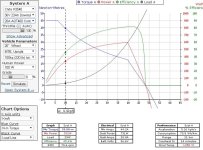
If you reduce the throttle to maintain 10kph, you'll still do no better than ~65%:
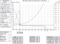
Ask it to accelerate from stationary (0.8kph is as low as that simulator goes) up a 10% grade, and >95% of the 527Ws you pour in will be wasted, converted to heat:
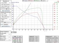
DD hubs don't like low speed.
liveforphysics said:The forces end turns make on the tooth are in equal and opposite thrust-axis orientations on the rotor so they don't contribute towards rotational torque in the axis we care about for vehicle motion.
The (physical) forces acting (via the conductors) on the tooth of a stator, acting in any direction, do not contribute to torque. It's a stator, it doesn't rotate. BLDCs do not derive their torque via Lorentz forces.
The electric field within and around the those (sections of) conductor (stator coils), do induce magnetic fields within the core of the tooth they surround, regardless of their orientation. Only proximity counts.
The greater the density of magnetic flux within the tooth, the greater the cross-linking with the fields of the permanent magnets in the air gap, and the greater the torque produced.
liveforphysics said:You can easily show this by winding a tooth that has end-turns that hang down however many feet away from the motor you wish, and it makes no difference in phase amps per amount of torque (but does increase copper loss).
See my earlier post that disproves that theory.
Me again 
Interesting summary on different ebike motors. Unfortunately it was mostly wrong. Clearly you favour geared hub motors, though.
I note your simulations showing how apparently poor DD hub motors are lacked a comparison to a geared motor.
Also the last simulation was especially interesting: You attempt to make your point about how poor the efficiency apparently is on a DD motor by showing it momentarily (check the acceleration - 17kph/s) fully loaded (45Nm) at 6.5rpm giving 5.8% efficiency. Well, there's not much surprise there as you're one step away from simulating an unloaded motor spinning up from rest. Guess what - starting at 0rpm gives 0% efficiency!
Alan B
100 GW
It is unfortunate that the simulator has a curve called "efficiency", since it continues to confuse people, and be mis-interpreted. That is not the efficiency curve of the motor. It is only motor efficiency at one point in the graph, where acceleration is zero. Everywhere else it is not motor efficiency.
Efficiency is power to do work / work accomplished.
That curve is power in / work accomplished.
Unfortunately power in has two components, power to do the work plus power to accelerate.
So the calculation becomes (power to do work + power to accelerate) / work accomplished. This is not motor efficiency, except at one single point.
The power to accelerate component throws off that calculation everywhere except at that single point in the graph where the acceleration is zero.
Everywhere else on the graph this "missing power term" causes this calculation to be something other than "motor efficiency", and for people to incorrectly think the efficiency of the motor is lower than it actually is during acceleration. It is a simple calculation, but the result is not motor efficiency over the speed range.
Calling this graph "efficiency" is confusing and misleading, and nearly everyone who looks at this graph is misled.
It is basically the same as a combustion engine miles per gallon curve made with the throttle stuck fully open. A vehicle might get say 50 mpg at 30 mph. But the graph made when the throttle is fully open will not pass through 50 mpg at 30 mph. The fuel flow rate at that point in the graph is related to the max fuel it can accept at that speed, not what it takes to travel at 30 mph. Most of the fuel is being consumed for acceleration. To find out what fuel it takes to go 30 mph we must reduce throttle until there is zero acceleration at 30 mph, and then we have the answer for that single point on the graph. We must repeat this experiment over for every speed to get a graph of efficiency vs speed.
When repeating this experiment over for each speed, for the electric motor or the gas engine, we will find the same thing - the efficiency at low speeds will rise to much higher values.
So the fundamental basis for this theory, that the efficiency of the motor is very low at low speed, is incorrect.
In the one case you mention that the efficiency with low throttle (when not accelerating) is 65%. I didn't check that, but it may be correct. However saying that while accelerating the efficiency is lower, is not correct.
Alan B said:It is unfortunate that the simulator has a curve called "efficiency", since it continues to confuse people, and be mis-interpreted. ...
Damn! And to think I thought I was being clever by using the tool so oft recommended around here (despite that I have reservations about it) to make my point.
So, let me try a different way. I'll get back to you.
Similar threads
- Replies
- 17
- Views
- 3,107
- Replies
- 15
- Views
- 2,177
- Replies
- 9
- Views
- 1,228


