Alan B said:
There is usually more than one approach to analysis of a problem, and they should all produce the same answer (or nearly so, within the accuracy of their approximation). I suspect that either Lorentz calculations or magnetic attraction calculations will, when done correctly, produce the same torque result.
Thanks for trying Alan.
I suspect that people get away using Lorentz torque calculations on reluctance torque motors, because in essence, both derive from the same inputs. The field from the magnets interacting with field created by the current in the coils. But, as with that MIT Lazar scooter example, they perform the Lorentz torque calcs, build their motor and when it doesn't perform quite the way they planned, they fudge it by adding more turns, or removing a few, or use a different gauge wire, to get the characteristics they really wanted.
They eventually get what they want, and never go back to work out why they didn't get what their math predicted first time.
That MIT example is classic, and the formula they use quite amusing:
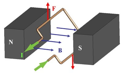
The field strength for Neodymium magnets is pretty close
to 1T, which makes the math easy. Since there are 30 windings per tooth, 2 teeth per phase, and
2 phases active at any given time, 120 windings contribute to the overall electromagnetic
interaction. Ideally, if the steel can carry it, the total current in all the loops combined (1200A)
interacts with a 1T field on each side of a tooth. The total force produced by this configuration is
therefore given by:
F = (10A)(120)(2)(0.0254m)(1T) = 61N.
This is a pretty high estimate of the force the wheel could produce at 10A
They are assuming that two 1/4" thick N42 neodymium magnets 3.438" apart will create a uniform 1T field between themselves; where the reality is that the closest turn to the magnets on the inner layer gets little more than 0.1T, and those furthest away gets less than 1.5e-3T.
Their only saving grace is that the concentrating affect of the iron cores in the solenoids, transfers the field created by the coils (end-turns and all) directly to the airgap to interact with the fields from the magnets.
It ain't Lorentz force, but it does derive from the same to basic inputs, and by eliminating (most) of the 1/R^3 fall of in the flux density, the calculation comes passably close to reality. Of course, if they included the forces from the end-turns, it'd get closer; but hey, they can always fudge it:
We probably won’t pick the exact right number of turns on the first try, but we can measure the performance of the first motor and use it to tweak the windings. Table 1 shows some possible scenarios and what we might be able to do to accommodate them. Motors are very forgiving, so it’s unlikely that we will make a motor that just completely doesn’t work, but this will help us figure out how to make it better in just one iteration.
Table 1: Possible scenarios after motor testing and the course of action that could be taken. --- Scenario Possible Course of Action --- Why?
Motor works perfectly on the first try. -- Celebrate --- Because.
Motor speed is good at 36V, but the torque is too low --- Heats up too much if we try to push more current. --- Use thicker gauge magnet wire or double-stranded magnet wire, but keep the same number of turns. The number of turns determines the back EMF, which also sets the top speed at a given voltage. So if the speed is good, we should keep the same number of turns and just make the wires themselves larger to carry more current.
Motor speed is too fast at 36V and torque is too low. --- Use the same gauge wire, but wind more turns. --- This will simultaneously decrease the top speed at 36V and increase the torque, since the total number of amp-turns contributing to the magnetic interaction will increase. This is sort of like increasing the gear ratio.
Motor torque is fine, but the speed is too fast. --- Use a lower voltage. --- Why would something ever be TOO fast?
Fag packet calculations and fingers in the wind. Why not.
Thanks again.
Buk.

")


.jpg")