• Howdy! we're looking for donations to finish custom knowledgebase software for this forum. Please see our Funding drive thread

Eric's Project #002

Beagle123 said:
Hey Xter:

Thanks for that great advise on batteries. The article you linked to said this:
The Milwaukee Emoli packs have been working out great when used in an application that doesn't require the latest and greatest lipo cells.

I assume he's talking about discharge rate? In terms of capacity, they are comparable to all lipo cells right? What is the chemistry of these cells?

Hey Beagle. Seems he's probably talking about discharge rate or weight. Emoli's are heavier than Lipo's and the 15C discharge rate is lower than the best lipo's. The chemistry is lithium manganese (LiMn). Lipo's are still the standard in applications requiring the absolute best capacity for least weight, like RC airplanes. The main downsides to lipo compared to either LiMn or LiFePO4 of course are safety and longevity.

Also, if I understand correctly, the LiFePo4 cells have approx 40% less energy by volume? This would be bad for me considering I'm lacking space.

That's about right. Each 26650-sized emoli cell holds 10 watt-hours of actually-usable energy (3.8v 2.6ah); each same-sized A123 cell holds 7 watt-hours of actually-usable energy (3.2v 2.2ah); regular lithium cobalt (li-ion or lipo) because of the strict 80% DoD limitation, have about the same volumetric energy density as LiMn, but in a lighter package.
 
Beagle123 said:
Do y'all know how much performance I would lose by using double the amps and half the volts? I know higher volts is better but by how much?

As you know I'm going to be using that same motor (MY1020Z3), so I have all the calculations for it. If you go to 56 volts and drop below 25 amps for the controller you will actually REDUCE the peak efficiency because you will be starving the motor for current. I'd suggest 25 amps if you are running 56 volts and be sure to adjust your gearing to adapt to a peak rpm above 5000 rpms. I'm staying with 48 volts to be cautious, but I'd love to hear about how 56 volts works out. Just don't go above 25 amps and you will have no problems. (the heat profile looks great... no overheating should be expected)

You don't usually lose anything when you go up in voltage, but handling the higher rpms can be rough... :shock: With the built in gear reduction and a big rear sprocket you should be fine. The #35 chain size allows a rear sprocket as big as 114 teeth.

P.S: What's wrong with that other motor? $450 reasons... :eek:
 
hey you are using that 6.67:1 ratio gearmotor right? you dont even need a large rear sprocket you probably need something like a 8:1 overall ratio from the motor to the rear so a 12t sprocket on the rear wheel would be fine you should actually just use the deraileur and all on the rear like safes bike, that would give you some awesome low speed torque in the low gears.
 
xyster said:
The main downsides to lipo compared to either LiMn or LiFePO4 of course are safety and longevity.

regular lithium cobalt (li-ion or lipo) because of the strict 80% DoD limitation, have about the same volumetric energy density as LiMn, but in a lighter package.


I can see the wisdom of using the Milwaukee Packs now because you can get a safer battery that lasts more cycles and you're only adding a couple of pounds of weight with no increase in volume.

Excellent info again.

In researching this, I realized that the most important factor is convenience, and battery management. These lithium batteries all deliver excellent power, and they're all comparable, but getting a good setup is critical.

The Milwaukee pack offers its own BMS, so instead of having to deal with 5 cells, you can deal with one 28v cell. That's a huge upgrade to me. The simplicity is the biggest selling point.

But I've been brainstorming about these battieries, and I've come to the conclusion that we should design a battery pack from the ground up. It seems to me that a good solution to the BMS problem is charging the cells individually.

Would you agree that charging each cell individually is the optimum situation?

If I understand correctly, you could just connect all the positives together, and all the negatives together and run an 8amp charger at 4.2 volts until current almost stops flowing.

The problem is that you then have to reconfigure all the connections for a 10s X 8p 36v pack.

I've been thinking that if I made a plastic box that exactly fit the batteries in rows and columns then you could make a grid. Then you insert the batteries so the positive is up on one row and the negative up on the next. Then if you connected the rows vertically, you'd have them in parrallel, and diagnally would make them in series. Or perhaps there's a way to make a 8 X 8 square plug.

You could then have a riding plug that creates your 36v pack, and a charging plug to charge at 4.2v, and a diagnostic plug to test the voltagess of each cell.

The starting poing is to have a physical container that makes a grid of connections.

I'm sure I'm not the first to think of this.

Are you with me?
 
Lessss said:
Batteries are going in the square box area yes? Will they slide in from top or side?


Hi Lesss

I was planning to insert them from the top because I want the sides to be complete welded pieces for strength. If I have to do any cutting, I'll do it from the top.

Hopefully, I can just insert each battery pack through the opening without cutting the hole bigger.
 

Safe and Dirty:

I was going to start with the 600w Unite gearmotor, but I decided I was just going to fry it, and I don't want to hear it scream as it dies. I want a bigger motor that easily handles the amps.

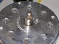
Unfortunately the motor I wanted (Mars brushless) in 9 inches in diameter so it won't fit. Then when I was unhappy about that I realized that I can get the 1200w 48v Unite motor (just sitting in my garage) to work. I finally got it throgh my thick head that all I have to do is install a 1/2 inch sprocket onto the 12mm shaft.

I hope it works.
 

Attachments

  • DSCN0535.JPG
    DSCN0535.JPG
    60.8 KB · Views: 2,702
there is no way to hold it on though, well actually if you mean the type with set screws you could just screw them into the flat areas where the wrench goes to tighten the nut. 12mm is pretty close to 1/2" but the sprocket will still not be in the exact center it might not be much of a problem though.
 
Yea dirty. I found #35 sprockets with set screws and choice of number of teeth at McMasterCarr.com. Also they were only $12. The info said that they were 3/4 inch thick. That should fit the shaft. Mine should be arriving in a couple of days. I'll be the guinea-pig.
 
Shocks Installed

I drilled the holes for the shocks today. I'm trying the "just drill a hole and put a bolt through" method for the shocks. I took dirty's advise and ordered bushings, but the ones for the shocks were just skinny little pieces that didn't look like they'd do any good. So I drilled a 3/8 inch hole and threaded the one on the inside so the bolt would be threaded into the inside connection thus having full contact. I put an additional bolt on the bolt sticking through. When I do the final assembly, I'll put lock-tite on the aluminum and nut and tighten it firmly so the whole thing locks together as one piece. That should be good because the shocks have rubber connections to the bushings. So, for example you can flex the shocks even when they're bolted in. THere shouldn't be too much stress on the connection.

The bushings for the pivot point look great, except I ordered them too short. The length=total length not length of shaft.

In this first picture look at the black circle around the top hole on each shock. That's solid rubber. The inner gold metal hole is a bushing. WHen you tighten them into place the sides fully contact that little gold bushing, locking it into place, but the shock will still flex in every direction because of the rubber.

 
Beagle123 said:
Unfortunately the motor I wanted (Mars brushless) in 9 inches in diameter so it won't fit. Then when I was unhappy about that I realized that I can get the 1200w 48v Unite motor (just sitting in my garage) to work.

:arrow: I also have both of those motors.

One thing to know... the 1200 watt motor has a higher resistance value (about 0.312 ohms) and so it tends to heat up FASTER than the geared motor. (about 0.227 ohms) The 1200 watt is built to absorb the heat better by simply being heavier, but since it naturally tends to heat faster anyway it almost cancels out the advantage.

And don't forget you will need to radically rethink your gearing... without the 9:60 geardown you will have to compensate for that. The MY1020Z3 is a great motor, I think you should stick with it. The heat profile is very good if you stick to 48 volts and about 30 amps for the regular controller. You could jump up to 40 - 50 amps if you switched to MCL like me.
 
If you do the math and set up the gearing for a top speed of around 30mph, the bigger motor should do great.

If you set up the gearing for a top speed of 50mph, the motor will smoke.

The shock absorbers look like they have rubber mounted bushings on the ends. If you bolt them tight, the rotation caused by compressing the shocks should be completely handled by the rubber. My old Honda SL-125 used rubber bushings for the swingarm. Never needs lube and immune to dirt and water.
 
you should be able to get about 34 mph with that motor at 1200W, if you need help with the math for the gear ratio i can do it for you i would just need the exact circumference of the rear wheel. the good thing about gearing it like that is when you run the motor at a lower voltage to go about 20mph the motor will be operating very close to the peak efficiency zone, on mine i geared it so at top speed the motor runs at peak efficiency, bad move, if i want to get a reasonable range i need to keep it at about 20 mph and at that speed the motor is running past the peak efficiency point too close to the no load area. with my new bike ill have a higher ratio(7.5 - 8:1) so that at top speed the motor is running at its max rated power and at about 20 mph its running at peak efficiency.
 
It's a good thing that this bike is not really built for speed... it makes things a lot easier. Since you are trying to avoid too much speed you can gear it way down like Dirty D suggests and just let the motor spin itself into the no load area at 20 mph. One of the best things about electric motors is that you can artificially set your own self regulating "speed limit" by using a low enough gear ratio... (it's the way to sell a bike that obeys all the laws and yet the buyer can easily change everything the moment they get it home)
 
well it wouldn't really be geared conservatively its geared for the max possible speed at its max rated output, its just convenient that at about 20 mph(steady state) the motor would be at peak efficiency.
 
Heres a guy selling some magmotors you might be interested in: LINK
 
Yes, my mistake. I thought it was one of these which could be suitable perhaps but not worth the bother maybe: http://www.robotcombat.com/marketplace_magmotors.html
Man this is sure an interesting bike!
 

Fetcher, safe, and dirty, I'm in total agreement with you that I should shoot for a high gear ratio. I've learned on my current bike that 4th gear is faster than 6th gear because the motor gets higher rpms, and draws less amps.

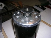
By the way my wheel is 22 inches total. I know how to do the math for the ratios. At this point I'm leaning toward a 14 tooth front sprocket (#35 chain) (see pic). And I guess I'll try to fit the 114 tooth go-kart sprocket on the back. That should be about 8:1 ratio. That makes my speed 24mph @ 3000 rpm. I think that may be higher than necessary. But also I'm using a gear hub for more gearing.


By the way, the 1/2 inch sprocket seems to fit the 12mm shaft. I'm not sure if its centered, its hard to tell. Perhaps fetcher can weigh-in becasue he's done this before.


Attachments

  • DSCN0545.JPG
    DSCN0545.JPG
    38.5 KB · Views: 2,649
Here's Where I am Now

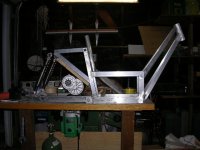
I'm cutting pieces to make the back triangle that the shocks attach to. I cut the diagonal piece too short, as you can see. My major concern with this operation is leaving enough space between the motor and the diagonal, so when I go over a bump, and the shocks compress, the motor doesn't hit the frame. I have a 3/4 inch piece of plywood as a spacer. Since the shocks are 3 times further away from the pivot than the motor, the shocks would have to compress 2 1/4 inches (3 X 3/4 = 2 1/4) for the motor to hit. I don't think the shocks can comress that far. Can they? It still looks a tiny bit too close to me.

How far do shocks normally compress?

These shocks are super stiff. I"ve lowered most of my weight onto them and I can barely make them budge. THey supposed to be adjustable, but I don't know how do adjust them, or even what "adjustable" means (stiffer? longer?) The shocks on my current bike compress 5/8 inch when you sit on it.

Also, safe, I can easily change motors with this bike because it has a nice platform for the motor. I could change to the other motor in 1/2 hour, provided I don't need to squeeze for space on this part.


Attachments

  • DSCN0544.JPG
    DSCN0544.JPG
    45.8 KB · Views: 2,638
Any reason why you can't just move it up?
:?:
 
if you're using a internal gear hub like safes then that motor isn't going to work, you would need something like a 200 tooth rear sprocket to have a 8:1 ratio in the highest gear.
 
TylerDurden said:
Any reason why you can't just move it up?
:?:

Or move the motor back?
 
By the way, the 1/2 inch sprocket seems to fit the 12mm shaft. I'm not sure if its centered, its hard to tell.

just touch the leads to a 9V battery and watch the sprocket from the top to watch how much it wobbles, even if it only wobbles a little bit though you're going to hear an annoying rhythmic sound coming from your chain.

i might try to mount my sprocket like you did but i think i would buy a 3/8" shaft one and have it bored out to 12mm, do the threads go all the way through the holes or are they just in the bottom of the hole?
im going to probably use a 11 or 12t sprocket though then i will only need about a 85t rear sprocket, the 114t ones are the most expensive, ive seen the 85-90t ones for $14 the 114t ones above $40.
 
TylerDurden said:
Any reason why you can't just move it up?
:?:

Hi Tyler:

I'd like to just move it up, but I also wanto to make more thickness in the frame where the back part meets the battery box. If you look at the picture, there is a triangle back piece meeting the square battery box. If you move the triangle up about 1 1/2 inches, the triangle and the square would be meeting at their corners. Luckily that line is a solid 1/8 inch thick square tube, so its very strong, but I'd still like to slide the triangle down so there's more thickness connecting the two shapes. I'll have to arrive at a comprimise. Looking at the picture, I'm thinking I could easily move it up 1/4 inch
.


if you're using a internal gear hub like safes then that motor isn't going to work, you would need something like a 200 tooth rear sprocket to have a 8:1 ratio in the highest gear.


That sounds about right. I was computing based on a fixed hub, knowing the gears will allow me to go 50% lower, and 75% higher. I figured my speed at 24mph. That means my lowest gear is 12mph, and my highest gear I haven't even thought about. I will probibly try to make my lowest speed 10mph or so.


might try to mount my sprocket like you did but i think i would buy a 3/8" shaft one and have it bored out to 12mm

That's a great idea!! I can "kill two birds with one stone." I'll get a 10 tooth sprocket and bore it out to be 12mm.

Xter: if I move the motor back, it will make it worse. Moving it forward would help, but then it could hit the tire. If I"m in a real pinch, I could change to smaller tires for more room.
 
Back
Top