Chelsea - welcome, welcome. We'll try to do you proud with this project. I'm back to trolling for money again but things continue to move forward.
Thanks for those links Matthijs. I'm getting close to taking off the rear wheels and tracing the electrical lines going to those rear calipers. I'll try applying a set DC voltage from a power supply - should be interesting. Right now they spin freely.
Greg, I've read about people using 3D cameras or something like that to take a physical object and then get it into a CAD program. Never done it before though!
Probably time for a mini update, picture heavy as usual.
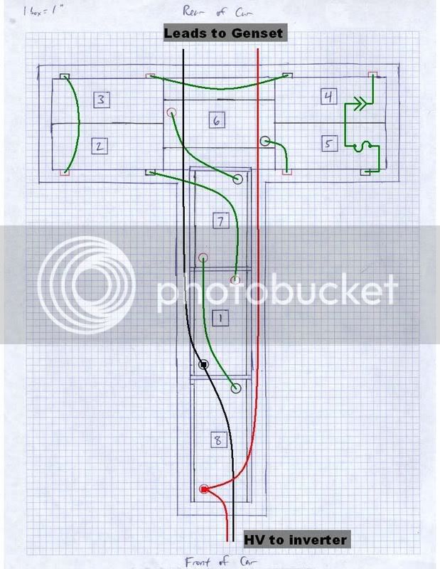
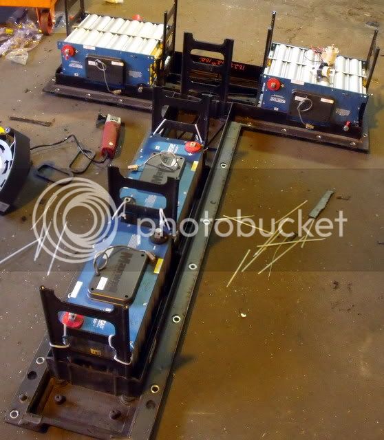
I spent the time waiting for the HV hardware to arrive by installing the capacitor modules into the battery tray. Here's the general schematic for laying them in.
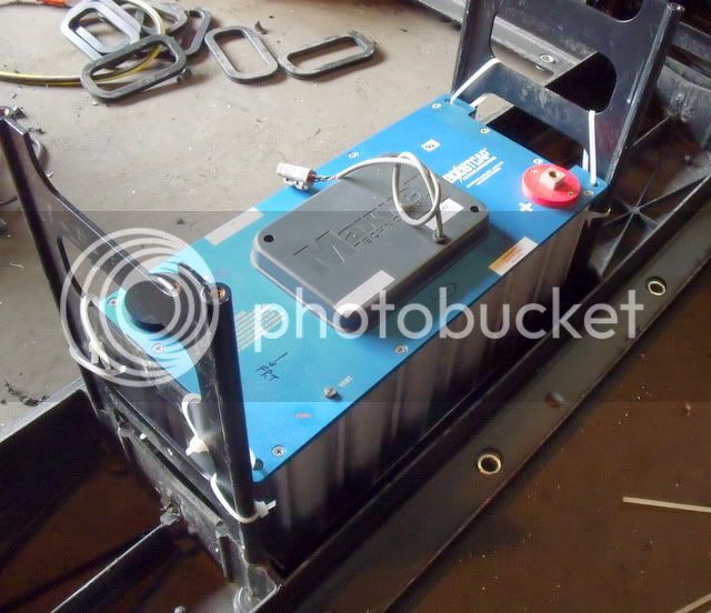
I installed the #1 module, and it fit in with minimal adjustment. The zip ties will hold it down and centered.
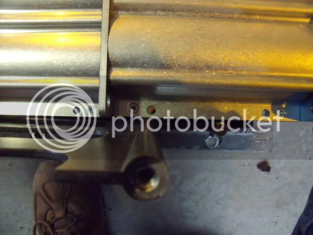
Modules 2-5, which are arranged back-to-back laying on their sides, took a lot more work. These posts were about 3/16" too far in on each side:
Drilling, hacksawing by hand, etc. allowed me to get them in. They're secured to one another with four bolts per pair.
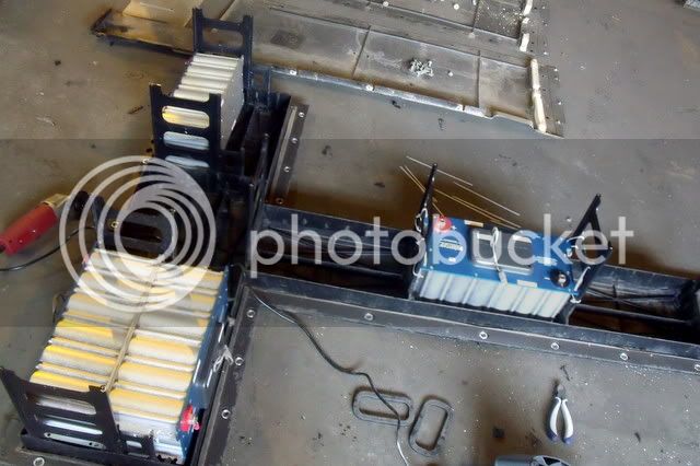
Here's modules 1,2,3,4,5, and 8 installed. 6 and 7 are the ones I assembled cell by cell, so I'll be building a plastic case for each of them before installing.
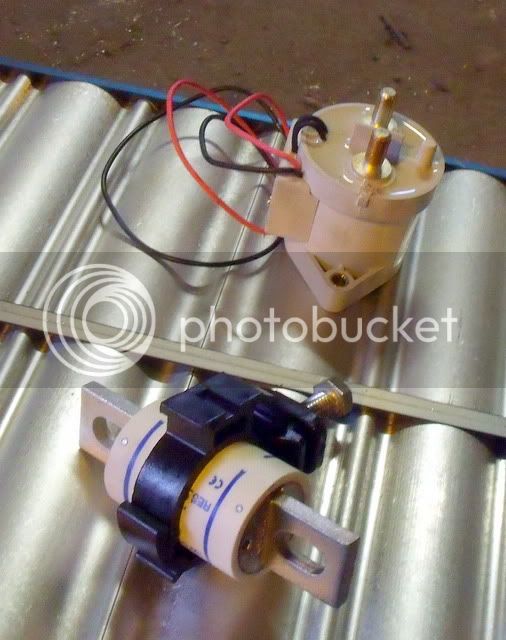
Here are the contactor and the fuse (in a fuse holder). The contactor is a Kilovac EV200 series, operated with a 12 V coil. The fuse is Ferraz-Shamwut, 400 A, 500 VDC semiconductor type. They'll both go mid-pack, between modules 4 and 5. I'll have access to them through the hole behind the driver's seat.
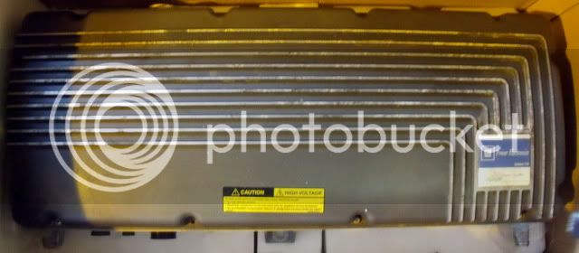
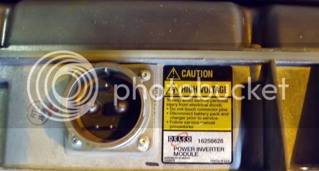
Here's the inverter, still in the box. It's got a monster connector receptacle (type 32-1), which uses two 1/0 connections. This is the main DC power input to the motor inverter. The smaller wires aren't used anymore.
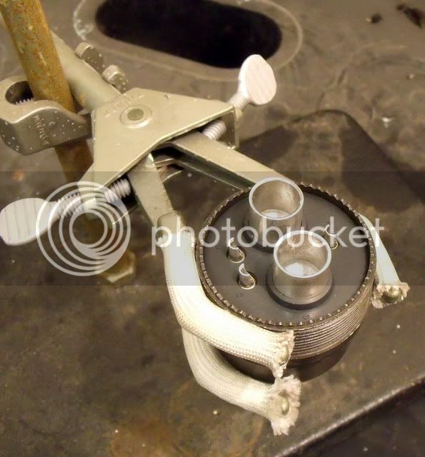
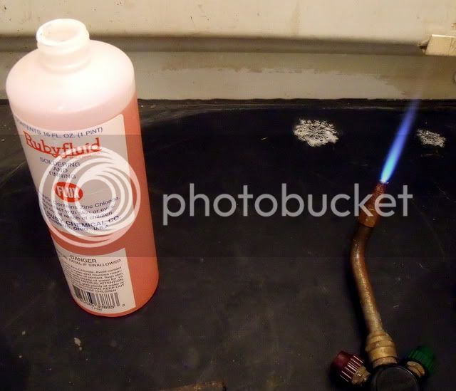
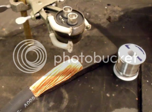
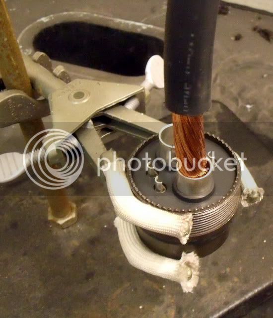
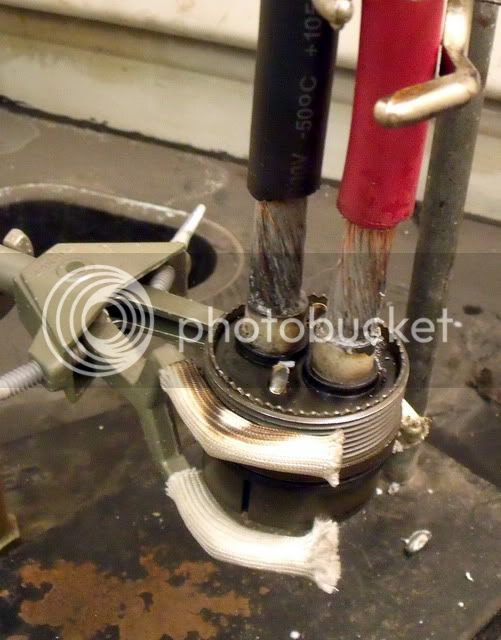
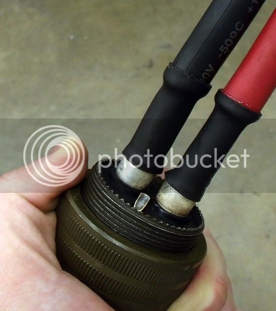
The connector plug needed those 1/0 cables to be soldered in, and since I only ordered one I had to do it myself. Here's the slideshow. I'll spare you the description for now.
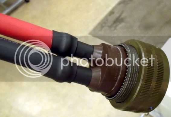
The outer cap is on it now. If I can finish wiring up the capacitors and remake my charging supply (220 VAC line, 220 V variac, bridge rectifier), I can get 300+ VDC to the inverter and light it up.