Fardriver controller serial protocol reverse engineering

E-Andreas

10 mW
Joined
Apr 6, 2022
Messages
21
This thread is intended to reverse engineer the fardriver standard serial protocol (same connection as the PC Software is using).
Over the next few month I will share my progress as I am learning.
If you aware of any existing work that can be benifitiary to this process please share.
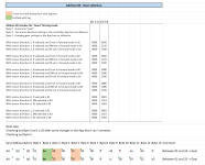
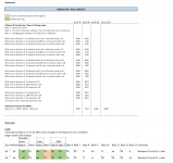
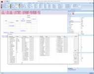
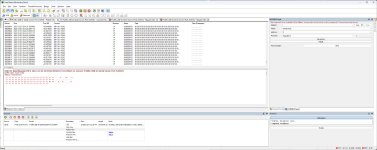
Attached a fill of the serial communication recorded during the use of the PC App for Fardriver.
I expeced that the the progress will be slow in the beginning.

Regards
Andreas
 

Attachments

  • SeriellerSniff30.10.2023.xlsx
    13.5 KB · Views: 44
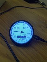
  • IMG_4503.JPG
    IMG_4503.JPG
    2.1 MB · Views: 31
Found RPM for Speedometer calculation.

Next up:
Looking for power reading (Watt).
I am not sure sure that the info regarding the power reading provided by Dougf is correct, I have to test again.
wr250f conversion


RPM.png
 
1: I decompiled the FarDrive APK and obtained MotorNet.dll. When I examine the code, there's a method [SendRs232Data WriteAddr] like this:

private void SendRs232Data(byte mcmd, byte scmd, byte va1, byte va2)
{
byte[] array = new byte[8];
array[0] = 170;
array[1] = mcmd;
array[2] = ~array[1];
array[3] = scmd;
array[4] = va1;
array[5] = va2;
array[6] = array[0] + array[1] + array[2] + array[3] + array[4] + array[5];
array[7] = ~array[6];
MessagingCenter.Send<MainPage, byte[]>(this, "WriteParaMeter", array);
}
// ConnectPage.cs(975): this.SendRs232Data(4, 192, 85, 85);
// ConnectPage.cs(990): this.SendRs232Data(4, 1, 85, 85);

private void WriteAddr(byte[] data, byte addr, byte len)
{
data[0] = 170;
len += 4;
data[1] = 192 + len;
data[2] = addr;
data[3] = addr;
byte b = 63;
byte b2 = 127;
byte b3;
for (b3 = 0; b3 < len; b3 += 1)
{
int num = (int)(b ^ data[(int)b3]);
b = (b2 ^ this.crctablehi[num]);
b2 = this.crctablelo[num];
}
data[(int)b3] = b;
data[(int)(b3 + 1)] = b2;
MessagingCenter.Send<MainPage, byte[]>(this, "WriteParaMeter", data);
}
//BaseMessagePage.cs(2774): this.WriteAddr(array, 160, 2);
//ConnectPage.cs(178): this.WriteAddr(array2, 171, 2);


2: Looking at the firmware ND72300_13_C_A24.hex in IDA, it's quite messy.

I haven't found a good way to deal with this yet.

I would like to control the motor speed (power) using UART.
Nice work. One easy way of controlling the power might be using an arduino to modulate the throttle output.

I am using an arduino (actually an esp32 now) to read the controller data from a votol and send it to my kt lcd8h display on my ebike.
I will need to do something similar on my electric motorcycle with my fardriver nd72300 s12. Although I would much rather decode the one-line output and get my data from there.
 
Anyone have experience with the CAN bus output? My controller claims to have it configured and enabled, but I get nothing on CANH/L
1702151521303.png

I think that if CAN is really supported it would be a better option for interfacing with MCU compared to UART (depending on situation of course). Ive done some CAN-FD stuff with the esp32 so this would be similar.
 
Anyone have experience with the CAN bus output? My controller claims to have it configured and enabled, but I get nothing on CANH/L
View attachment 344035

I think that if CAN is really supported it would be a better option for interfacing with MCU compared to UART (depending on situation of course). Ive done some CAN-FD stuff with the esp32 so this would be similar.
In order to have CAN working the controller must be ordered as a CAN Version. CAN is not the standard config.
 
Does anyone know if the one-line (YXT) output is really a 12V based LIN Bus as used in cars or just a form of RX UART? I ask this before buying a mcp2003 as I am not 100% sure it's necessary.
 
In order to have CAN working the controller must be ordered as a CAN Version. CAN is not the standard config.
Ah bummer, wonder if the can transceiver just was omitted or purely fw..
Does anyone know if the one-line (YXT) output is really a 12V based LIN Bus as used in cars or just a form of RX UART? I ask this before buying a mcp2003 as I am not 100% sure it's necessary.
Measure on the oscilloscope so be sure
 
Even easier if you happen to have any form of Windows computer with a line input (or buy a cheap USB one).


Note that for any signals outside the voltage / impedance range of a typical soundcard, you'll need to build a piece of simple electronics to buffer it's input and protect it. This article has some info on that
and there are other site as well.
1702781101045.png 1702781123435.png

There are other softwares out there for various OSes, as well.
 
I ended up buying an MCP2003 LIN transciever chip just to be on the safe side and I'll give it a gone one of these days to see if I can get my data for the display.
 
I was trying to use my Logic Analyzer on the Single-speed/One-line bus and this is what I picked up.

Here are some shots.

1702847358266.png1702847416644.png
 
I played around for a little bit with the one-line output on the votol on my ebike (protocol should be the same as with fardriver as they use the same displays and are made by the same company) and it seems to me like it's not really LIN Bus.
Thinking of the use case being a one-way transmission from the controller to display I think it's just a one-way UART.
Why would this company invest in using LIN bus when uart should be cheaper as it doesn't require any 12V psu and a lot less logic.
Using a multimeter the highest voltage I got was a bit over 2v over the single wire signal.
Judging by the output from the logic analyzer fMax ~ 9.6 khz I used a 9600 baud and this is what I get:
1703099239902.jpeg
I've tried running it through a mcp2003 lin transceiver but the result was the same and no LIN frames were identified.
Also the votol specs state 0-5V for the single wire output.
The output changes with wheel movement, hitting the brake, so I might be on the right path.
However the data doesn't look right with mostly 00 and F0 on standby.
I will investigate further.
As this is my very first attempt with decoding stuff like this it's very likely that I'm doing something wrong, so if anyone can help, please do.
Thanks.
 
Last edited:
I asked my aliexpress seler (that sold my votol) for documentation on the format used for "one-lin" and (for my surprise) he was kind enough to provide me this document. I am sharing this with everyone hoping it helps.
 

Attachments

  • 一线通液晶协议Y34&Y29_translate.docx
    34.7 KB · Views: 55
A little update. I played around a bit with the "one wire" display output and was able to decode the data with a simple arduino nano.
Here's some rough test code, nothing fancy, just a simple proof of concept but it works well for me.
Protocol documentation in previous post.


#define sif_pin 2
short battery = 0;
short current = 0;
short currentPercent = 0;
short rpm = 0;
long faultCode = 0;
bool regen = false;
bool brake = false;
unsigned long lastTime;
unsigned long lastDuration = 0;
byte lastCrc = 0;
byte data[12];
int bitIndex = -1;
void setup() {
Serial.begin(115200);
pinMode(sif_pin, INPUT);
lastTime = micros();
attachInterrupt(digitalPinToInterrupt(sif_pin), sifChange, CHANGE);
}
void loop() {
// put your main code here, to run repeatedly:
}
void sifChange() {
int val = digitalRead(sif_pin);
unsigned long duration = micros() - lastTime;
lastTime = micros();
if (val == LOW) {
if (lastDuration > 0) {
bool bitComplete = false;
float ratio = float(lastDuration) / float(duration);
if (round(lastDuration / duration) >= 31) {
bitIndex = 0;
} else if (ratio > 1.5) {
// bit value 0
bitClear(data[bitIndex / 8], 7 - (bitIndex % 8));
bitComplete = true;
} else if (1 / ratio > 1.5) {
// bit value 0
bitSet(data[bitIndex / 8], 7 - (bitIndex % 8));
bitComplete = true;
} else {
Serial.println(String(duration) + "-" + String(lastDuration));
}
if (bitComplete) {
bitIndex++;
if (bitIndex == 96) {
bitIndex = 0;
byte crc = 0;
for (int i = 0; i < 11; i++) {
crc ^= data;
}
if (crc != data[11]) {
Serial.println("CRC FAILURE: " + String(crc) + "-" + String(data[11]));
}
if (crc == data[11] && crc != lastCrc) {
lastCrc = crc;
for (int i = 0; i < 12; i++) {
Serial.print(data, HEX);
Serial.print(" ");
}
Serial.println();
battery = data[9];
battery = data[9];
current = data[6];
currentPercent = data[10];
rpm = ((data[7] << 8) + data[8]) * 1.91;
brake = bitRead(data[4], 5);
regen = bitRead(data[4], 3);

Serial.print("Battery %: " + String(battery));
Serial.print(" Current %: " + String(currentPercent));
Serial.print(" Current A: " + String(current));
Serial.print(" RPM: " + String(rpm));
if (brake) Serial.print(" BRAKE");
if (regen) Serial.print(" REGEN");
Serial.println();
}
}
}
}
}
lastDuration = duration;
}
 
Back
Top