Building the Best Controller

It has been a long time since our last comprehensive summation; therefore let us review what was discussed in brief, and the changes/directions that have manifest as a result.

MPS
Voltage Limit is set to 150V, though the design plan allows for 100V through component loading options.

FET
There has been a tremendous and informative conversation in the past weeks.
  • 6- and 12-FET versions discussed; which has priority?
  • Drop TO-220 support
  • Embrace TO-247
  • Provision for Off-Board FETs
  • PCB Plating up to 3 or 4 ounces
  • Insulated Substrates
  • Bus Bars
  • FET candidates Categorized:
    • 75V: IRFP4368PBF up to 195A, TO-247
    • 100V: IRFP4468PBF up to 195A, TO-247
    • 150V: XFK360N15T2 up to 360A, TO-264
    • Defer Amp demands exceeding spec to Off-Board support.
  • Candidates for Off-Board considered:
    • MMIX1T550N055T2: 55V, 550A, Square Package
    • MMIX1F520N075T2, 75V, 500A, Square Package
  • FET Board Architecture examined:
    • If 12-FET designed, layout to be two parallel rows of 6 FETs
    • Sandwiching configurations: Brief
MCU
  • Lots of discussion on the concepts at large; generally there are two camps:
    • One MCU that does it all up to 2WD
    • Central CPU driving dedicated wheel controllers in a 1:1 relationship. This is the leading contender.
  • AVR is most often mentioned followed by PIC and ARM.
  • Which is better: 8-bit architecture or greater?

Changes to Feature Specification:
These changes are pending. Unless there are concrete reasons to do otherwise I will update the specs by EOD next Monday 11/22.

MPS:
  • Maximum voltage = 150V (should be locked)
  • Maximum Current: Onboard = 150A; Support greater range Off-Board (should be locked)
  • Lock remaining features for Version 1.
FET:
  • Add Board #2 & #3 derivatives from the Sandwiching configurations discussion but do not lock until we have consensus.
  • Add Driver circuitry to spec to support Board #2 option but do not lock.
MCU:
Conversations are too fluid and embryonic for definitive conclusions; no changes.

Actions:
The achievable tasks that we can do with what we know right now are as follows…

MPS:
Develop Prototype Circuit and BOM. Once this has been completed and vetted we should move to Prototype design and layout, consider any pending showstoppers, and then move to limited production for stuffing and evaluation. Call it: "MPS Version 1.00 – ALPHA." :wink:

FET:
We are close to a consensus. We could and should adopt the dedicated motor controller per wheel with a master unit orchestrating the entire show. This would forward a forked development path of 6- and 12-FET boards specifically tailored to meet the lesser and greater needs of all interested factions, including the Off-Board support. It is a lot to bite off and doubles the challenge; though considering the overall epic objectives at stake we’re simply adding one more lap to the 4-lap race. To that end…

Using TO-247/264 onboard, develop a high-level circuit design to submit to the team developing the MCU, and resolve the significant details between (FET) Boards #2 & #3. In addition, we should adopt a different naming convention than #2 & #3; maybe FET Driver & Daughter would be more fitting, yes?

MCU:
I think we are still too fluid in this arena. More discussion is warranted. Consider though…
  • The Tools of Development should be easily obtainable (low cost).
  • The programming language is not difficult to master and does not require licensing fees or limitations of use, such as the development of Consumer Interface for parameter modification through whatever device we elect.
  • The Device Feature set maps closely to the MCU specification without significant additional hardware support.
  • The Device Feature set is not overloaded with or duplicates that of common functionalities with other devices e.g. GPS or Mobile Phone.
PCB Common Module Interface:
Now is the time to start putting this together. Let’s divvy this up into functional blocks: MPS, FET to FET, MCU to FETs, and Reserved for future.

Plush Features:
User Experience and Interface should be fleshed out as we move forward, learn, and understand what the hardware will do; we have a good map though we won’t know the topology precisely until we cross that bridge. We’ll continue to accept input. We need to support other developed hardware such as the CA and the BMS et al; conversely - we don’t need to be distracted with the business of re-engineering those wheels.

Questions?

Much appreciated, KF :D
 
Hi,

As I mention before I would use a ARM core, from the performance point of view, you can't compare with a Pic or AVR. The Cortex m3 should be big enough. It's a 32bit core,Harvard-Architektur, has a HW multiplier in 1 clock, a true Nested Vectored Interrupt Controller...

There is a new eval board for only £6.80. The Part Nr is: STM32VLDISCOVERY

1824325-40.jpg


â–  STM32F100RB microcontroller, 128 KB Flash, 8 KB RAM in 64-pin LQFP
â–  On-board ST-Link with selection mode switch to use the kit as a stand-alone ST-Link (with SWD connector)
â–  Designed to be powered by USB or an external supply of 5 V or 3.3 V
â–  Can supply target application with 5 V and 3 V
â–  Two user LEDs (green and blue)
â–  One user push button
â–  Extension header for all QFP64 I/Os for quick connection to prototyping board or easy probing

Shane Colton is also use a STM32, please look at: http://scolton.blogspot.com/
 
That is an impressive board for the price!

Earlier in this thread there was some agreement that whatever micro was chosen should have the motor control hardware on-chip. Does this particular micro have this?

This includes such things as:

Six PWMs with guaranteed non overlapping output, programmable dead times and synchronous updating of all the control registers.

Hardware comparators for pulse by pulse overcurrent monitoring directly tripping the PWM off as well as comparators for reading sensorless crossings.

ADCs with integrated differential inputs and adjustable gains for monitoring battery and phase current values.

Hardware inputs that trip the PWM outputs into "safe states" for inputs like the ebrake or other fault conditions.

I know some ARMs have this, but not sure if this one does. The AVR ATMega32M1 has this, and a number of PIC processors have this as well.

Or the collaboration could decide this was not required after all.
 
Bump.
 
Im interested in your high capacity controler and have been looking to see if you guys have made any progress.Im interested in building, buying or trading for one to go with my 22 k outrunner.Thanks Carl
 
I would recommend against going with an applications processor (ARM9, Cortex-A series, ARM11, etc), since
- the BOM count for support chips is high (external flash, ram, multiple power domains, etc)
- the caches and MMU make hard RT difficult to analyze, and typically require a full general-purpose OS (Linux)

Cortex-M3 is a fine choice for a CPU core. The STM32F103 series do not include motor-control PWM's with the features you need, but the Stellaris line from TI (nee Luminary) does. They even sell a BLDC reference design kit. There are also some older ARM7 MCU's with motor-control PWM peripherals.
 
I've been looking over this thread with some interest, but only in the last few days, so please forgive me if I managed to miss this discussion earlier :) What are your plans for safety circuits?

- If your ebike is coming down the mountain at some kind of crazy fast speed, what prevents an uncontrolled battery charge through the commutation diodes by the motor's back-emf?
- If there is a FET failure or other explosion/fire in the controller, what do you plan on using to disconnect the battery (breakers, fuses, etc)?
- What is the plan for discharging the DC filter caps after shutdown?
- Will there be inrush current limiting when connecting the batteries?
- What is the battery reverse-polarity protection plan?
- Is the user expected to keep the batteries connected most of the time, or will the user physically disconnect/connect the batteries? What protects the user from battery voltage during this operation?
 
jdb said:
I would recommend against going with an applications processor (ARM9, Cortex-A series, ARM11, etc), since
- the BOM count for support chips is high (external flash, ram, multiple power domains, etc)
- the caches and MMU make hard RT difficult to analyze, and typically require a full general-purpose OS (Linux)

Cortex-M3 is a fine choice for a CPU core. The STM32F103 series do not include motor-control PWM's with the features you need, but the Stellaris line from TI (nee Luminary) does. They even sell a BLDC reference design kit. There are also some older ARM7 MCU's with motor-control PWM peripherals.
Understood. I think that going with a 16-bit microcontroller is better for the more advanced functions that an 8-bit. There is the spec option to support both trapezoidal and sinusoidal (however accomplished) to consider. I’d like to explore this line of thought further should you have the time.

More... KF
 
jdb said:
I've been looking over this thread with some interest, but only in the last few days, so please forgive me if I managed to miss this discussion earlier :) What are your plans for safety circuits?

- If your ebike is coming down the mountain at some kind of crazy fast speed, what prevents an uncontrolled battery charge through the commutation diodes by the motor's back-emf?
- If there is a FET failure or other explosion/fire in the controller, what do you plan on using to disconnect the battery (breakers, fuses, etc)?
- What is the plan for discharging the DC filter caps after shutdown?
- Will there be inrush current limiting when connecting the batteries?
- What is the battery reverse-polarity protection plan?
- Is the user expected to keep the batteries connected most of the time, or will the user physically disconnect/connect the batteries? What protects the user from battery voltage during this operation?
Addressing each bullet point:

  • Uncontrolled battery charge: BMS or safety shunt-resistor. But what is the chance that a rider will be at the top of the hill with a full battery pack – unless they live there? I once measured the gain on my pack after dropping over 1000 feet over 8 miles and I picked up 0.5V on a large 60Ah pack. However – I burned up about 1.0V getting to that hill. I think this would be an edge-case at best.
  • FET Failure: In case of a controller explosion I’d wager the short has already created the open circuit; far too late to do anything. However – the avid hobbyist could always place an inline fusible link for additional safety. Otherwise, fuses/breakers of the magnitude required are beyond the scope of the controller specification.
  • Discharge: Filter caps leak on their own accord within seconds. That said there should be discharge pads or posts on the PCB; this is part of the original specification.
  • Inrush: Protection may or not be on board since that is a feature relating to the actual battery connection, and possibly involving the Controller’s On/Off Switch. Good discussion point.
  • Reverse Polarity Plan: Run away! Seriously, that is a good point. I imagine that a diode would work, but I am sure there is more involved with protecting the board, and there might be circuit losses.
  • Last Bullet – Part 1/Battery Drain: Personally, I keep my batteries connected all the time for several reasons: Eliminate potential wear & tear on the battery connectors, eliminate risk of charring through connection, and the internal controller losses are very small (in the mA range). The drop in total pack voltage can be addressed with a simple top-off minutes before a ride with a good strong charger.
  • Last Bullet – Part 2/Liability: As for protection of battery voltage from the user, that would be the providence of the person responsible for wiring. The design of the controller’s circuit boards and enclosure should follow standard industry practices meeting and exceeding consumer safety requirements. Unfortunately this would be difficult to enforce if a hobbyist assembles the kit on their own without knowledgeable skill. The only way around that is with a liability waiver upon purchase of the BOM – that is if the hobbyist was able to buy the kit from an organization or legal and accountable entity.

All good questions. KF
 
Understood. I think that going with a 16-bit microcontroller is better for the more advanced functions that an 8-bit. There is the spec option to support both trapezoidal and sinusoidal (however accomplished) to consider. I’d like to explore this line of thought further should you have the time.

I say this as a 3-phase UPS firmware engineer, which has 2 consequences. I have a pretty good idea of what works in a 3Ph inverter, and unfortunately there's only so much I can really do to aid this project due to IP overlap with my employer. So here goes my brain-dump of stuff that is obvious to my employer and all of our competitors, but might be useful to someone just getting started:

Must haves: rich PWM peripheral on the uC. In the front-page marketing, the vendor will call it a motor-control PWM. In the technical reference manual for the chip, you should see:
- at least 3 pairs of complementary channels
- programmable dead-time between channels
- Each pair of channels should be center-aligned with each other. This is almost always accomplished by using a an up/down counter to form a triangular carrier, with toggle actions on compare-match events.
- hardware-driven external enable pin, with lockout. This allows an external GPIO (or an internal analog comparator) to immediately deenergize all of the gate drive signals. You normally use this to control modest-speed current limits, on the order of a microsecond or maybe a few hundred nanoseconds. For desaturation protection (10's of nanoseconds) you should normally rely on the gate drive circuits themselves.

The uC should also have a nice ADC. Important features here are that the ADC can autonomously follow a sequence of samples without intermediate programming by the user program. So, you should be able to program a sequence of muxed channels that the ADC will sample, and only trigger an interrupt when all of the samples in the series have been taken. Typically such uC's also have a DMA engine to help manage the sequencing. 10-bit sampling resolution minimum, 12-bit or more would be better, but you can manage with only 10.

A wider MPU core will always be better. Top-of-the line luxury would be something with a floating-point unit, like Cortex-M4, AVR32 uc3c, or TMS320F28x. Second tier down is anything with a RISC-ish 32-bit core, including AVR32, PIC32, Cortex-M3, and ARM7. Price-wise, that already gets you plenty of choices for 10 USD or less in modest quantity. For a hobby project, it will be better to pick a part that is supported by either GCC or LLVM rather than one of the free-as-in-beer compilers for other platforms. Someday, you will exceed the project size limits for the freeware version of the proprietary compiler if you go there, and having a zero-cost full-featured compiler keeps the barrier to entry for new devs low. The advantages of a wider CPU core with a higher clock speed is that it gives you more arithmetic throughput for things like automatic hall effect sensor calibration, modified trapzoidal commutation, PLL-based rotor position sensing, and so on.

Once you've picked an MCU product line, don't bother guessing about how much flash or ram you'll need. Just get the biggest part storage-wise in that line. As a hobby project, the 3-5 USD/part is not worth optimizing out, especially if you are talking about sinking ~ 20 USD/phase into main drive silicon.

So, why not dsPIC or AVR with motor-control peripherals? Its another optimization problem: the 32-bit cores only cost a few bucks more than their 8 and 16-bit counterparts, but they bring much more arithmetic throughput, clock speed, and convenience. Remember that doubling the width of the core tends to more than double the real-world arithmetic throughput. Internal control variables will tend to track much more precision than is really available in the inputs and outputs. So by buying a wider core, you are effectively spending 2-5 USD/part to buy faster development time.

Paralleling up multiple inverters for a single motor is Hard. It's doable, but increases the development effort by 4x or more. Paralleling up multiple inverters on a one-per-motor basis is comparatively easy. You don't actually need much communication between modules, and can get away with none. But if you do want some comms, isolated CAN bus is the way to go. It is specifically designed for reliable use in high-noise environments. Anything else will eventually run into problems with cable routing and/or high-frequency electrical noise. They aren't insolvable, they just slow you down and get in the way.

Now, that covers the wants for the engine of the "brain" board. But what is more important, for division of labor purposes, is to define the electrical interface between the power module and the control board. Do you want the analog filtering on the control board or the power module? How much bandwidth must the power module provide for its feedback signals to the control board? What range of voltages will the power module present to the control board? Does the power module need to provide analog signals that include or exclude the ripple current in the frequency domain? Most of these questions are really the same design point, but they all must be covered.
 
Hello,
I wonder what happenned to this awesome thread ?...
 
Lagoethe said:
Hello,
I wonder what happenned to this awesome thread ?...
It has been partly superseded by other efforts, each advancing to their own tune. However much has been learned in the hiatus therefore this Phoenix may rise again. For the moment, my prime direction is focused with another endeavor and shall remain so until August. However I would suggest reviewing the open issues. Perhaps together we may continue. :)

Best, KF
 
Hello.

I'm retired from electronics and real time embedded systems.
In my first job i worked on measurement systems and regulators for industrial synchronous machines ( 10 to 400 MW ) so I know them well.

Recently I discovered e-bikes, and I was horrified by their controllers.

I've a better one in my Whirlpool washer for energy economy and noise reduction.

They are silly using trapezoidal command on e-bikes which need a great autonomy, and have a legal power limit. They loss about 20 25 efficiency.

Trapezoidal command produce big torque ripple ; that don't help rotor synchronization when starting on 10 % climb.

They are silly taking of hall sensors for pulling.

I don't need a motor for flat roads.

Torque ripple produce vibrations than can break spokes, when frequency is the same as spoke's resonance frequency


The motor eat a lot of current for nothing, it seems shitting as a tired old cow pulling a cart


Trapezoidal command produce a lot of harmonics ; so they have more stator iron power loss

Trapezoidal command is a barbarous command. Listen your motor, it sound bad.

The Best Controller for me can only be a FOC command controller.

MCU

The first step when designing an embedded system is "charge evaluation " to choose the processor you need for your application.

Microprocessor's manufacturers did the job for us.

For Motor control with FOC command , you need a real time processor and you need more ADC channels with very hight conversion range, and very fast PWM.

So you can forget 8 bits processors they are too slow for computations

You can forget multimedia processors, they are not real time processors.

You can choose an ARM Cortex M3 or R4

But with ARM you need an OS, and you can't programm them in ASM the faster language for real time.

We don't need a linux like OS to drive a motor.

We don't need data and program files and file systems.

We don't have to call processes and libraries in the memory to run them.

Motor's controllers always do the same job , but very fast.

An OS will slow your application, then you get OS bugs, and you will spend a lot of time to compile your OS before it run's well. Configuration and initialization for ARM is a hard job, if you don't have professional software tools. They cost a lot !

Microprocessor's manufacturer have designed processors dedicated for motor control ( someones run faster than a ARM Cortex M3 ). They are optimized for this job.

They don't need an OS, and manufacturers give us.

- developpement tools

- libraries for motor control

- monitoring tools

Why choose another range of processors ?

The wrong way for designing an embedded system is to choose the processor you know well, the one you learned at school.

We have more interesting job to do than reinventing the wheel : learning FOC command, and setup, optimization.

Personal design :

In the streets, between cars and pedestrians, on flat, I need a pacific e-bike.

For climbing ( i live in the mountains ) I need a great torque

So I will enslave the torque to the slope with an inclinometer and a speed limiter for down hill.

I've other ideas for my two wheels trailer, it push very hard when downhill. And I need something like an electric handbrake for hill start.

For me it seems better to use another processor for other "gadget" tasks than motor control. Let it work !!!

Otherwise the watch dog could get out of the niche, with trying various features.

You can develop these other tasks later and separately to avoid bugs in your motor control system. And you can use your bicycle without this secondary processor.

When looking for manufacturers dedicated processors i've selected two.

Microchip with ds33pics 16 bits and the free IDE MPLAB

Texas Instruments with C2000 32 bits ( fixed point or floating point ) and free IDE Control Suite which support C2000 processors.( and Code Composer Studio very useful for on line doc, you should try it. ).

No ! 32 bits is not over needs ( I used to work with fixed point 32 bits ) and for FOC command we have a lot of computations, with hight precision.

Finally I choosed Texas.

http://focus.ti.com/lit/ml/slyb165c/slyb165c.pdf

http://www.ti.com/ww/en/motor_drive...motor_control_controller_c2000_32_bit_mcu.htm

They have an evaluation kit , but limited to 6 A. http://focus.ti.com/docs/toolsw/folders/print/drv8312-c2-kit.html

The next one will be a 60V 60A ( it's enough for my bike ) it will cost 299 $


> DRV830160-C2-KIT - $299 Coming 2011
>
> . DRV8301-based pre-driver for 8-60V with 60A MOSFETS
> . Includes PiccoloT controlCARD and can accept any
> MCU-based controlCARD
> . Professionally developed GUI and ? rmware
> . Open source: BOM, schematics, Gerbers, controlSUITET software
> and Code Composer StudioT IDE
> . Control: FOC Sensored (provide own shaft encoder), Sensor less
> (SMO 2-shunt current), speed and torque closed loop
>
>
> PMSMs are used in applications requiring precision
> control and low torque ripple, such as robotics, servo
> systems and electric power steering.

With the kit you have all the documentation, development and monitoring tools.

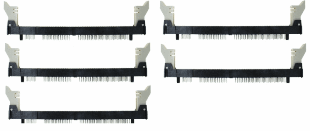
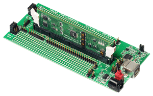
The processor is on a 1" x 4" board with 100 pins DIMM connector with some chips, there is an isolated UART, and you don't need an external jtag.

piccolocontrolcardrollover.gif


You can change processor board with others C2000 processors ( price 49 $ to 99 $ )

http://focus.ti.com/mcu/docs/mcuprodtoolsw.tsp?familyId=916&sectionId=95&tabId=2655&toolTypeId=1

dim100connectorrollover.gif


piccoloexperimenterskitrollover.gif


One board has two external very fast ADC, for very hight speed motors.

Isolation :

The Best Controler has isolation especially with hight current and inductances.

Sensors :

Why hall sensors burn in Chinese motors ?

there are no voltage regulator, zeners, capcitors, or Mov, near the sensor to protect it against peak voltage.

look at this one for automotive : http://www.vems.hu/download/sensors/1gt101dc.pdf


http://focus.ti.com/docs/training/catalog/events/event.jhtml?sku=OLT410007


FETs :

I think its better to use MosFETs Power modules than one, two, or three dozens of MosFets :lol:

They take less place, ( if you respect copper areas rules ) and have a very large base plate for heat dissipation. They are designed for a better heat dissipation.

You have less solders.

You can use a print-board with 105 µm thin copper for the power board (standard is 35 µm).

105 µm copper boards have specific rules for the size of "elements" you can't use it for processors sockets, but it's OK for power modules

You don't have low signal control wires beside hight current wires

For very hight power, more than 100 A, power connections don't need a print-board, and commands pins with a connector.

You can use current transducers to replace shunts and you get a good isolation.

Power module is good to avoid short circuits when you open the box.

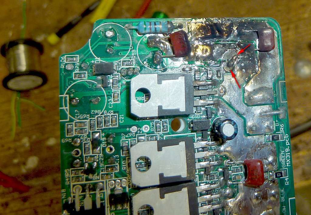
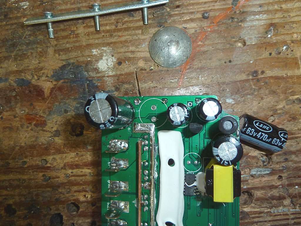
Look at this : during all my life in electronics I've never seen a shit like this .

p1030553t.jpg


p1030544.jpg


I'll add power module documentation later, it coast more , but it's a good way., but it's a good way.
 
Can you make your motor controller sized for TO-247 package mosfets and components rated for at least 100V? :D I'm serious. People would buy them from you for $500 US no questions asked. Even $1000, I'm sure.
 
jdb said:
...

I say this as a 3-phase UPS firmware engineer, which has 2 consequences. I have a pretty good idea of what works in a 3Ph inverter, and unfortunately there's only so much I can really do to aid this project due to IP overlap with my employer. So here goes my brain-dump of stuff that is obvious to my employer and all of our competitors, but might be useful to someone just getting started:

Must haves: rich PWM peripheral on the uC. In the front-page marketing, the vendor will call it a motor-control PWM. In the technical reference manual for the chip, you should see:
- at least 3 pairs of complementary channels
- programmable dead-time between channels
- Each pair of channels should be center-aligned with each other. This is almost always accomplished by using a an up/down counter to form a triangular carrier, with toggle actions on compare-match events.
- hardware-driven external enable pin, with lockout. This allows an external GPIO (or an internal analog comparator) to immediately deenergize all of the gate drive signals. You normally use this to control modest-speed current limits, on the order of a microsecond or maybe a few hundred nanoseconds. For desaturation protection (10's of nanoseconds) you should normally rely on the gate drive circuits themselves.

The uC should also have a nice ADC. Important features here are that the ADC can autonomously follow a sequence of samples without intermediate programming by the user program. So, you should be able to program a sequence of muxed channels that the ADC will sample, and only trigger an interrupt when all of the samples in the series have been taken. Typically such uC's also have a DMA engine to help manage the sequencing. 10-bit sampling resolution minimum, 12-bit or more would be better, but you can manage with only 10.

A wider MPU core will always be better. Top-of-the line luxury would be something with a floating-point unit, like Cortex-M4, AVR32 uc3c, or TMS320F28x. Second tier down is anything with a RISC-ish 32-bit core, including AVR32, PIC32, Cortex-M3, and ARM7. Price-wise, that already gets you plenty of choices for 10 USD or less in modest quantity. For a hobby project, it will be better to pick a part that is supported by either GCC or LLVM rather than one of the free-as-in-beer compilers for other platforms. Someday, you will exceed the project size limits for the freeware version of the proprietary compiler if you go there, and having a zero-cost full-featured compiler keeps the barrier to entry for new devs low. The advantages of a wider CPU core with a higher clock speed is that it gives you more arithmetic throughput for things like automatic hall effect sensor calibration, modified trapzoidal commutation, PLL-based rotor position sensing, and so on.

Once you've picked an MCU product line, don't bother guessing about how much flash or ram you'll need. Just get the biggest part storage-wise in that line. As a hobby project, the 3-5 USD/part is not worth optimizing out, especially if you are talking about sinking ~ 20 USD/phase into main drive silicon.

So, why not dsPIC or AVR with motor-control peripherals? Its another optimization problem: the 32-bit cores only cost a few bucks more than their 8 and 16-bit counterparts, but they bring much more arithmetic throughput, clock speed, and convenience. Remember that doubling the width of the core tends to more than double the real-world arithmetic throughput. Internal control variables will tend to track much more precision than is really available in the inputs and outputs. So by buying a wider core, you are effectively spending 2-5 USD/part to buy faster development time.

Paralleling up multiple inverters for a single motor is Hard. It's doable, but increases the development effort by 4x or more. Paralleling up multiple inverters on a one-per-motor basis is comparatively easy. You don't actually need much communication between modules, and can get away with none. But if you do want some comms, isolated CAN bus is the way to go. It is specifically designed for reliable use in high-noise environments. Anything else will eventually run into problems with cable routing and/or high-frequency electrical noise. They aren't insolvable, they just slow you down and get in the way.

Now, that covers the wants for the engine of the "brain" board. But what is more important, for division of labor purposes, is to define the electrical interface between the power module and the control board. Do you want the analog filtering on the control board or the power module? How much bandwidth must the power module provide for its feedback signals to the control board? What range of voltages will the power module present to the control board? Does the power module need to provide analog signals that include or exclude the ripple current in the frequency domain? Most of these questions are really the same design point, but they all must be covered.

Just coming back and rereading some old threads, the above comments from jbd are excellent. Thanks for coming by and making them!

I'm working again on my controller design, picking up from where I left off. I have decided to use CANbus, and have most of the schematic fleshed out. More fun ahead!

I bought a TI development kit, and spent time looking at other Cortex ARMs and it looks to me like going with those chips you may lose control of the project and become highly dependent on the vendor. Libraries, licenses, specialized tools, hardware manuals well over 1,000 pages long for one chip. So I'm going to forge ahead with one exception to jdb's advice, and try out the ATmega32M1 that I have, though I did buy some ATmega64M1 chips which are on sale at Newark under $4. I'm scoping my controller project to NOT do everything or attempt to tick every box, but instead to do Hall and Sensorless control WELL and with great torque based throttle modulation. My goal is to learn, and perhaps a later controller project will go farther into FOC etc. The 16 MIPs ATmegaxxM1 can do motor control with a few percent of CPU utilization, so we should have enough to do the few other things we need to do. Based on what I'm seeing the next step would be an ARM, but that's a pretty big step, especially when talking about making your own PC boards. I don't see the AVR32 going anywhere these days, and there are ARMs all over the place, so I will have to dig into their hardware at some point. The documentation is rather daunting, just figuring out how to route the motor control hardware to some external pins is a research project.

If anyone is interested in a TI ARM based motor control kit, drop me a PM. I don't think I want to get entangled with all their libraries and licenses.
 
Back
Top