Attached is a schematic for the ignition of a gas burner that I designed and put in service about 6 or 8 years ago. It is still working. Here is how it works:
U1A creates a pulse every two seconds that triggers the spark.
U1B creates an 8 milli-second dwell time in the coil. This works with the coil's inherent inductance and resistance to build the current in the coil. It is a cylindrical spark coil out of an old Ford. Circa 1960 or 1970. Typical junk box coil. Primary 1.5 ohms, 0.0060 Henries, Secondary 7500 Ohms 12 Henries Turns ratio 96/1
D3 is real important and real critical. Let me try to explain what goes on. The spark coil is a 100/1 turns ratio I think. A typical spark plug will jump at about 8 Kv in air at atmospheric pressure, this will reflect about 80 volts onto the FET from the flyback of the secondary reflected in the primary. Now think how the secondary rises with no plug. The coil will go above 30,000 volts to (theoretically infinity). At 40 Kv it is reflecting 400 volts back onto the FET. For a pulse detonation engine ignition system I designed, I used IGBT's with about a 390 volt breakdown diode (TVS) to save the IGBT.
What D3 does is when the seconday is open, and the voltage goes to the heavens, at about 200 volts it breaks down, and starts to turn the FET back on to control the run away flyback. It saves the FET. Without the secondary "constrained" with a reasonable spark gap you will blow the FET. This is why "certain" older cars would blow the ignition module when the carbon wires got old and bad. The secondary voltage went to the heavens, they overstressed the transistor/FET/IGBT and blew it. Detroit learned, and now there are some nice IGBT's with the breakdown diode incorporated in the design like the MGP15N40CL (which is the part I used in the Pulse Detonation Engine Ignition System.) I might make R7 a little bigger if I were hitting the over voltage clamp all the time.
Schematic below:
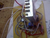
 Im collecting the parts for this :


