Jay64
100 kW
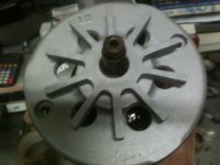
This is kinda small, hard to see, but it is the setup I have at the controller.


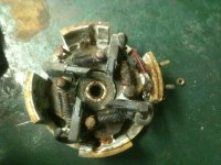
I was looking at the connections inside the throttle box. If the rest of the car looks like that, taking apart every connection and cleaning would be a good start. A wire brush or even sand paper might be needed.Jay64 said:fechter, thanks for the input. Are you talking about the connections on the contactor?
Mine is for this.fechter said:All right! Cart wars!
First one to the starting line wins.
fechter said:All right! Cart wars!
First one to the starting line wins.

fechter said:I was looking at the connections inside the throttle box. If the rest of the car looks like that, taking apart every connection and cleaning would be a good start. A wire brush or even sand paper might be needed.Jay64 said:fechter, thanks for the input. Are you talking about the connections on the contactor?
Did you find a wiring diagram that seems to match?