Miles said:I meant the motor drive pulley (large one) & freewheel .phyllis said:I don't understand... is motor concentric to crank spindle? Don't quite see it.Miles said:and hang the motor pulley/freewheel from that (supported by a bearing)? Too much crank offset?
The inner part of the motor drive freewheel is connected to the outer part of the crank/output freewheel.
The inner part of the crank/output freewheel is mounted on the bottom bracket spindle.
See: http://www.endless-sphere.com/forums/viewtopic.php?p=356222#p356222
More complicated to do than your present plan but it would give you dual isolation.
No, I don't think that would work for what I want to do - Two selectable reduction ratios for the motor, and two selectable overdrive ratios for the pedals. See if I've got it right:
His drawing is from the rear, mine is from the front.
His right freewheel is clocked opposite to the left fw.
Thus it is impossible to drive the right freewheel with the pedals.
But on mine, both freewheels are clocked the same way.
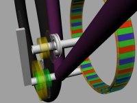
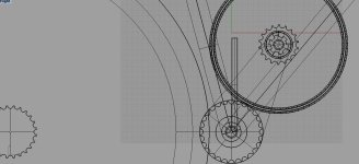
I've put letters on the pulleys to make it easier to refer to. C and D holds the rear wheel drive chain. Inside of fw1 mates to crank, outside mates to B. Inside of Fw2 hangs from B, outside mates to C.
View attachment biketranny-ABCD.png
Yup. that is a good idea.It might be wise to add a bearing between the outer freewheel and the axle, to take the radial load. Otherwise, it's cantilevered from the single bearing unit in the inner freewheel....

")